Slabs Floors
metal, concrete, steel, floor, fig, roof, fabric and construction
As shown in Fig. 101, the bracket is designed to take care of all stresses which may come upon it. The square bars in the top of the bracket take care of the tension stresses; the spirals take the compression; and the stirrups resist the tendency to shear. The proprietors of this sys tem claim to have devised this form of rein forcing to eliminate the cost of assembling the steel in the field, and furthermore, to have done away with the danger of unskilled workmen placing the steel in the forms in a haphazard manner—a very common occurrence and the cause of many failures. The columns of this sys tem are a unit for each story; the brackets are assembled in the shops ready to be placed in the forms, and the fabric for the floor is made in rolls the full length or width of the building.

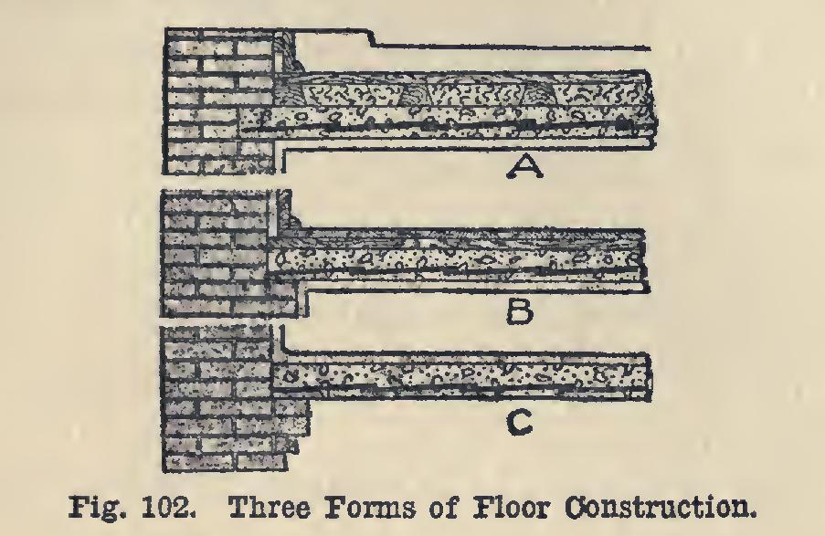
The three cross-sections, Figs. 102, A, B, and C, illustrate different methods of supporting re inforced concrete floors on brick walls, and different methods of finishing the floors. In A and B, the plastering is applied directly to the under side of the floor slabs. In B an under-floor is first nailed to the concrete, and to this under floor the finished floor is nailed.

Fig. 102, C, represents a plain reinforced floor with a surface finish of a richer grade of con crete. The ceiling below is formed by the cleaned under side of the floor above.
In each of these illustrations, the reinforcing agent is expanded metal.
Fig. 103 shows three types of short-span floor-slabs reinforced with rib metal.
Fig. 43 shows an anchored end bar reinforce ment which is claimed by some engineers to be a suitable construction in beams, girders, and thick slabs. The bars in this form of reinforce ment are round, with threaded ends fitted with nuts and large plate washers at each end. The bars are bent to shape before placing in the forms, and rigidly held in place. The number used depends upon the size of the member and the percentage of steel required. The anchor plates at the ends of the rods prevent serious slipping of the rod in the concrete, and provide a bond to resist the diagonal tension stresses set up in the beam.
This plan of reinforcement can be applied to continuous construction, as noted elsewhere, by carrying the ends of the rods over the tops of the supporting girders or columns into the ad jacent span, and anchoring them there in the manner just described.
The principles governing the design of rein forced concrete roofs are similar to those for floors. The reinforcing materials generally used for roofs are of light weight. The general construction is one of a combination of light steel shapes for the framework, upon which is laid some form of sheet fabric such as expanded metal, rib metal, closely woven wire fabrics, etc, The closer woven metals, when used, do away with the use of wooden forms, thus allowing the concrete to be deposited upon the metal directly; the holes in the fabric letting enough of the wet mixture pass through to form a good bond, and also to provide a rough surface to hold the plas ter or finish on the under side. Fig. 104 shows a
section of roof made by using a corrugated sheet metal. After the sheet metal is in place and firmly fastened and supported, it is spread over or plastered with cement mortar, forming a sheet or slab inches thick. The figure shows the general proportions of materials used in the mortar, and also the final covering of waterproof felt.
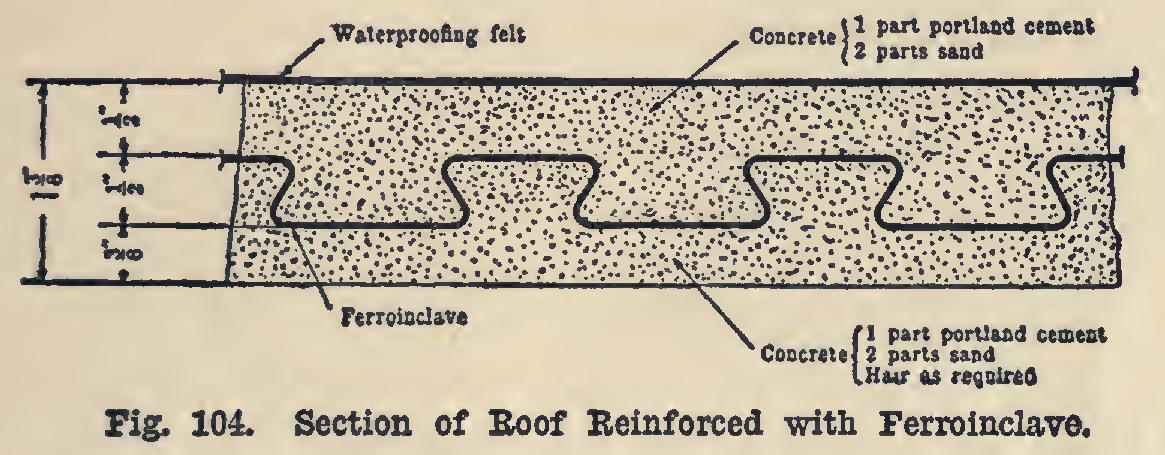
Fig. 105 shows a method of laying ribbed metal on a steel frame. In the use of ribbed metal, the rib should be laid upward on the roof. This places the bulk of the metal on the tension side of the slab, and also presents a smoother surface underneath to plaster on. Rib metal or woven wire fabrics should be fastened firmly to the structure at frequent intervals—say, every 24 inches, clips being provided for fastening to steel members. If a wooden frame is to be cov ered, the sheets may be nailed directly to the wood.

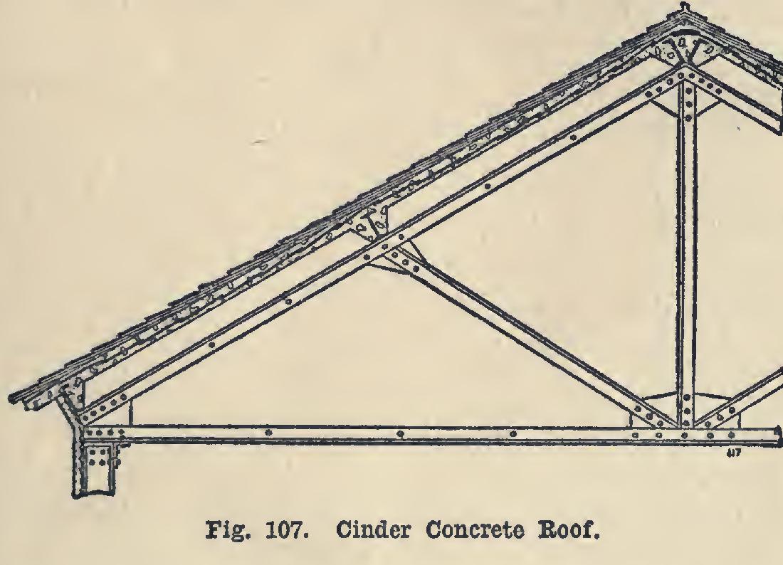
Fig. 106 shows a typical form of tile roof re inforced by concrete beams. The structure itself is of steel. The use of tile lightens the weight of the structure, yet does not interfere seriously with its strength or insulation against heat or cold.
When the coarser mesh grades of wire fabrics and wire-connected rods are used in roofs, forms are built below as in ordinary floor construction, the fabric laid over the supporting steel beams, and the concrete applied as in floor and slab work. An example of this form of construction is shown in the Peoples Gas Light & Coke Com pany Building in Chicago. Here a span of 10 feet, with roof live load of 50 lbs. per square foot, was filled with 4-inch slabs of concrete re inforced with "American fabric" without any rods underneath. The fabric extended contin uously from span to span.
Fig. 107 shows a form of reinforced cinder concrete roof, the reinforcing agent being ex panded metal stretched over the steel members of the framework.
In this method, purlins are spaced 5 to 8 feet apart, the slate roof being nailed directly to the cinder concrete within two to three weeks after placing same. This type of construction is in extensive use in the Navy Yards of this country and is regarded as being very satisfactory.