Abutments and Piers
bridge, pier, foundation, weight, abutment, load, top and walls
An interesting design of bridge abutment, of T-section, is illustrated in Fig. 72, the purpose of which is to effect an economy in concrete and in cost of forms as compared with the ordinary double-wall abutment of U-section. It has been used in the north abutment of the bridge carry ing the South Bend & Southern Michigan Ry. (an electric interurban line) over the St. Joseph River near Berrien Springs, Mich., where the conditions were favorable; and it was adopted on the score of economy. The foundation was hard pan, very hard to excavate, and the stepping-up of the footings for the stem of the T was readily formed in this material. The height is about 40 ft.; and by the ordinary formulas for a retaining wall, it would have required about twice the thickness of wall used, while the wings would have been heavy and the footings overlapped. It will be seen that, instead of two side walls, there is a single wall 6 ft. thick, carrying a canti levered slab 16 ft. wide, this slab or floor being reinforced by steel bars and provided with drainage holes so as to keep the ballast in good condition.

A U-abutment is so called because it is shaped like the letter U. The bottom of the U is repre sented by the bridge-seat, and the sides of the U are represented by the two tail-walls, or re taining walls, which retain the embankment. These walls may be of massive plain concrete entirely independent of each other, or they may be thin reinforced walls tied together. The abut ment of the highway crossing shown in Fig. 46 is of the latter type.
Arch abutments are used for very high abut ments, such as those of the bridge over the Mississippi at Thebes, Ill. They are of different styles and arrangement. A common type is shown in Plate 5; the two small approach arches are partially covered by the fill, and serve as abutments for the middle span.
A special type of hollow abutment is shown in Fig. 39, for the abutment of the Sangamon river arch bridge.
Bridge Piers. It has always been the en deavor of bridge-builders to make the clear span of their structures as large as possible; but since the cost of a bridge increases very rapidly as the span is made longer, it is customary to cross only the smaller streams and valleys without the use of intermediate supports between abutments. When a bridge is supported at some point be tween the abutments, the supporting structure is known as a bridge pier or tower. Towers are used only for high viaducts and short spans, and are seldom placed in mid-stream; piers are far more common.
From its definition it will be seen that a pier has to carry the vertical weight of the bridge and its traffic; it usually is placed in mid-stream, and must be able to resist the action of moving water and ice, and it must give the bridge an anchorage to prevent its overturning as a result of wind or vibration. To accomplish these ends,
a pier must have compressive strength, massive ness, and weight, and be designed for stability and bearing power. The civil engineer has these objects in view when he is planning the piers for a particular bridge, and a knowledge of his methods, as well as of the ways and means of getting the required results, should be of value to the construction man who carries out the work in the field.
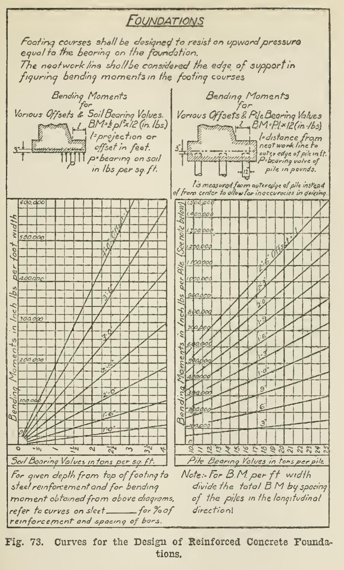
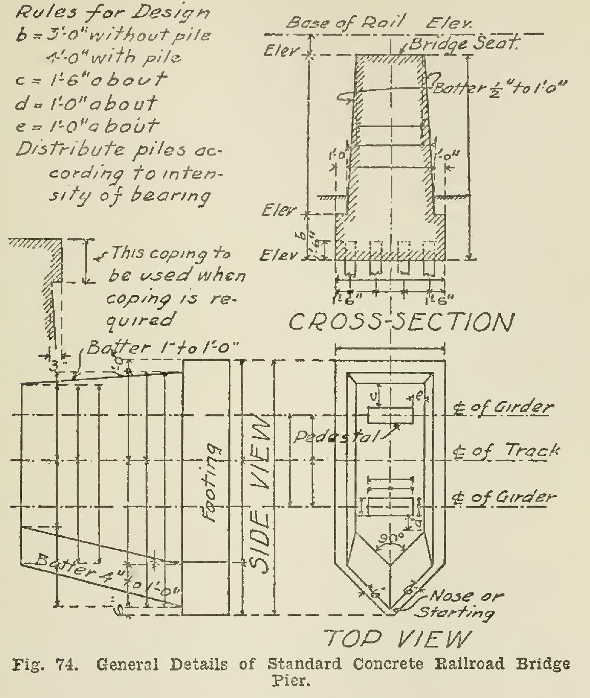
The first problem—to design the pier with sufficient compressive strength and footing area to transmit the load to the foundation and spread it sufficiently to prevent settlement—is attacked as follows : The part of the total weight of the bridge superstructure — trusses, girders, bracing, floor, etc., as well as the load of the trains, cars, vehicles, and people, which can possibly come on the piers—is computed. The steel or cast iron shoes or pedestals which rest on the top of the pier are then made large enough to distribute this load so as not to exceed the safe compressive strength of the material of which the pier is con structed. The size of the top of the pier—or the bridge-seat, as it is technically known—is gov erned by the size and position of these bridge pedestals. The dimensions of the pier are usually increased from the top downward, by sloping or "battering" the sides until the top of the footing course is reached. Footing course is the name given to the lowest part of the struc ture, and is the layer of masonry resting directly on the foundation. The bottom of the pier must be placed at such a depth below the surface of the ground or bed of the stream as will insure a firm foundation and safety from the effects of frost and the scouring action of the current.
The total weight of the bridge coming on the bridge-seat, together with the weight of the pier itself, constitute the total load on the foundation; and the area of the base of the pier must be made large enough to distribute this pressure accord ing to the safe supporting power of the particu lar foundation. The nature of the foundation is ascertained before the design is made, and the supporting power in tons per square foot is es timated. In many cases it is found necessary to use piles or more extreme precautions to give the pier a sufficiently firm foundation.