Bridge Floors of Reinforced
concrete, cement, mixed, floor, placed, inches, surface and steel
BRIDGE FLOORS OF REINFORCED The floor of a highway bridge is the pavement or the construction immediately underlying and supporting the pavement; the floor or deck of a railway bridge is the construction supporting the rails, or, in the case of solid floors, supporting the ballast, ties, and rails. In the case of concrete arches filled in between the spandrel walls, the fill takes the place of the decking. In the case of highway bridges with concrete floors, the floor is often provided with a wearing surface and used without any additional paving, thus effecting a considerable economy.
As a typical example of standard specifica tions for concrete bridge floors, we present those of the Ontario Highways Department: Specifications for Concrete Bridge Floors 1. Ferro-Concrete. Unless otherwise specified, the flooring shall be of concrete reinforced with steel. Wheel guards shall be of steel channels or of concrete, and such as will prevent the hubs of the wheels striking any part of the bridge. At each end of all spans over fifty feet, steel expansion aprons shall be used with concrete floors.
2. Material and Labor. All necessary material, la bor, appliances, and implements shall be furnished by the contractor, and shall be such as will secure a satisfactory quality of work.
3. Steel Reinforcement. The metal with which the concrete floor is to be reinforced shall be expanded metal wire netting, steel bars, or other metal approved by the engineer, and is to be completely surrounded by concrete; and it shall be so placed within the concrete, and shall be of such tensile strength, as to fully provide for the specified loading.
4. Thickness of Concrete. Sidewalks shall be four inches in minimum thickness, and shall be made with a slope of inch to the foot towards the roadway. The minimum thickness of concrete in the roadway shall be four inches at the sides, and five inches at the center.
5. Down Pipes. Down pipes, gratings, and other openings or fixtures shall be placed in the walk or road way wherever required, such openings to be measured continuously as part of the flooring.
6. Falsework. Temporary framework or staging shall be erected to support the concrete flooring while in process of construction, this framework to be firm and substantial, of suitable lumber, and, unless perfectly tight, shall be covered with tar paper to prevent the concrete dripping through.
7. Portland Cement. All cement employed in the work must be of a favorably known brand of Portland cement, and approved by the engineer. It shall be de
livered in barrels or equally tight receptacles, and, after delivery, must be protected from the weather by storing in a tight building or by suitable covering. The packages shall not be laid directly on the ground, but shall be placed on boards raised a few inches from it.
8. Mixing Concrete. The concrete shall be composed of gravel and Portland cement, mixed in the proportion of one part by measure of cement to five of fine gravel no stones of which exceed one and one-half inches in diameter. The concrete shall be mixed on a platform placed close to the work, by first spreading evenly a layer of gravel. Upon this shall be spread a proportion ate quantity of cement, and the two thoroughly inter mixed in a dry state. To this, sufficient clean water shall be slowly added, and the whole again thoroughly mixed and brought to the consistency of a stiff mortar.
9. Wearing Surface.
The sidewalk and roadway shall have a wearing surface one and one-half inches in depth, of sand and cement mixed in the proportion of one part by measure of cement to two parts of sand, the sand to be clean, sharp, of varying sized grain, and free from loam, earth, or other impurities. The sand and cement shall be first mixed in a dry state, then sufficient water shall be added to properly moisten, and the whole shall again be thoroughly intermixed. This top coating shall be applied to the concrete base before the latter has set, so that a perfect bond between the two will be secured. The surface shall be floated and troweled until smooth and even, and shall be finished with a toothed roller, or as directed by the engineer.
10. Placing Concrete. While the work is in progress it shall be so arranged that a steady supply of mixed concrete will pass from the mixing-box to the point where it is to be placed. At any time when the work is inter rupted before its completion, or at the end of the day, a wet covering shall be placed over the last layer of con crete; and before the work of depositing the concrete is resumed, this surface shall be thoroughly flushed with water to remove any doreign material which may have gathered thereon, and coated with a thin Portland cement grout. No cement shall be laid in wet or freezing weather.
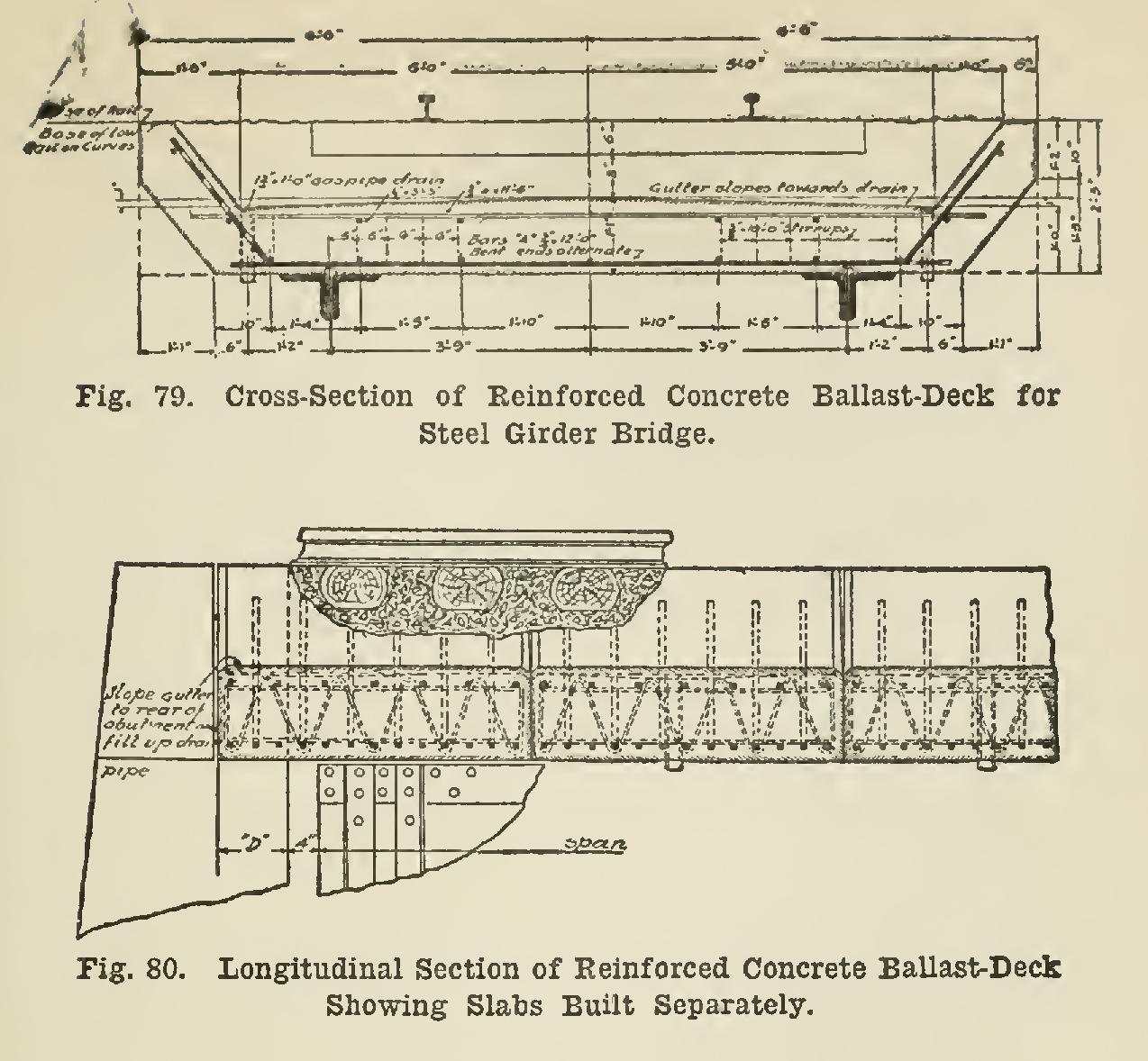
Figs. 78, 79, and 80 are sections of reinforced concrete ballast-decks for plate-girder railroad bridges. Fig. 78 shows the forms for building the floor in place. The floor shown in Figs. 79 and 80 is lifted into place in sections.