Pile Foundations
piles, wood, concrete, inches, square and fig
PILE FOUNDATIONS Figs. 19 and 20 show comparisons between the use of concrete and wood piles in foundation work. Fig. 19 shows the smaller number of Ray mond concrete piles required to sustain a given load as compared with wood piles under the same conditions. A shows the concrete piles in piers joined by concrete arches as built for the J. I. Case Plow Works, Racine, Wis. Single piles and a pier of four piles were weighted, the test load remaining on the piles for six days in each instance, without showing any settlement whatever.

B
shows the contemplated wood-pile plan for the same building, the cost of which, it is claimed, would have been fifty per cent more.
Fig. 20 is another illustration of the relative economy of concrete piles and wood piles. Ordi nary wood piles average about 12 inches in diameter at the top, and 113 square inches of head surface. Concrete piles, 20 inches in diam eter at the top, have 314 square inches of head surface, or 2.77 times that of wood piles. The taper of a wood pile is only about three or four inches from top to bottom, while the taper of a Raymond concrete pile is from 10 to 14 inches.
The illustration gives a fair representation of what may be saved by the use of concrete piles. The three concrete piles, each 20 inches in diame ter, have a bearing surface of 942 square inches, while the five wood piles, each 12 inches in diameter (which is a fair average) have a bear ing surface of only 565 square inches. Note the additional concrete required on top of the wood piles, which must also be cut off below the water line to insure their permanency. Furthermore, in using wood piles it is frequently necessary to drive sheet piling around the trenches in order to make the excavation to water line.
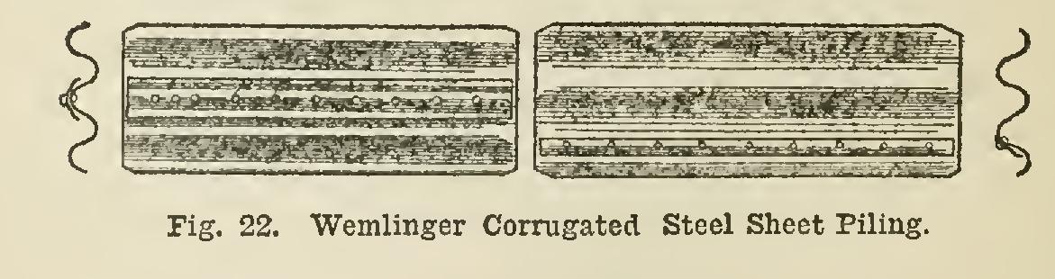
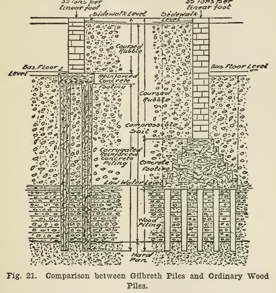
Fig. 21 shows a similar comparison in con struction work, showing the difference in the amount and form of foundation when Gilbreth piles are used instead of the ordinary wood piling.
The Wemlinger Corrugated Steel Sheet Pil ing is built in many types and sizes. The two types shown in Fig. 22 represent the single-lap and double-lap forms. The single-lap form is most suitable for sewer and water-pipe trenches, open cuts for railroad tunnels, foundations, trenches, and such general excavation work as does not require absolute water-tightness. The double-lap form is used for work requiring any degree of water-tightness, as in cofferdams, bridge piers, etc.
The clips shown in the figure provide for the locking together of the sheets so that they may be driven as a solid sheet. In some forms of this product, the clip is omitted, the piling simply overlapping one corrugation on each sheet.
The Jackson Interlocking Steel Sheeting is especially adapted for cofferdams, bulkheads, dams, bridge foundations, lighthouse founda tions, piles, caissons, locks, wharves, cribs, forts, shafts, shields for tunnels, and for any other con struction work in deep water where it is neces sary for the piling to be perfectly water-tight.
The sheeting can be driven through clay, sand, gravel, quicksand, and even into shale rock, and can be used over again repeatedly.
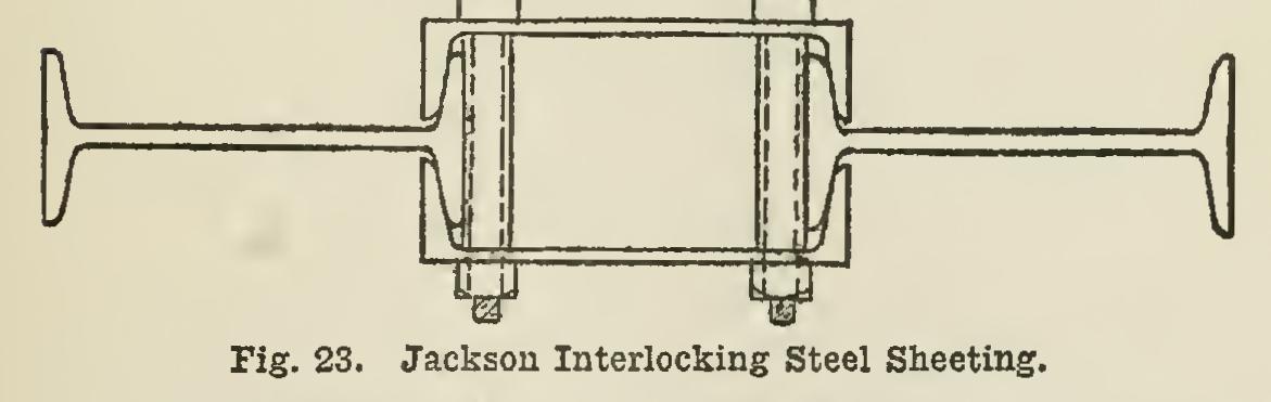
Fig. 23 shows a section of patent interlocking steel sheeting, Style No. 1. This is made per fectly water-tight by filling in the channels with clay or cement grout. It can be made up of either 15-in. 33-lb. channels and 15-in. 42-lb. I beams, weighing 49 lbs. per square foot, or 12-in. channels and 12-in. I-beams, weighing 40 lbs. per square foot; and is espe cially adapted for heavy construction work. In other styles of this sheeting, instead of clay or cement, wooden pieces are driven in between the channels, and produce a water-tight joint by swelling.