Rules for the Design of Railway Culverts
culvert, pipes, concrete, wing, cast-iron and walls
RULES FOR THE DESIGN OF RAILWAY CULVERTS Views. In general the following views shall be shown: A longitudinal sectional elevation along center line of culvert.
A complete plan of culvert.
A complete plan of footings.
A half cross-section at center line of track and at parapet.
An end view.
. . .
In detailing these views, the outline in Fig. 59 shall be followed in a general way.
Size. In giving the sizes of culverts, the width shall he named first, and then the height; for example, 12x8' indicate a twelve-foot width and an eight-foot height. By the height is meant the distance from top of paving to bottom of cover.
Footings and Struts. Wherever the bearing on the soil makes it necessary, solid floors shall be used. Solid floors should be avoided wherever possible, by extending the footings under the side walls.
Cross-struts at intervals of about ten feet shall be provided.
In general, the end struts and the footings under the wing walls shall be carried lower than the footings under the culvert barrel.
Joints. Transverse vertical joints shall be provided in culvert barrels about every forty feet.
Wing Walls. Wing walls under about 8 feet in height shall be made continuous with culvert walls. (See 30∞ wing, Fig. 62.) Wing walls higher than about 8 feet shall be made self-supporting, and a joint shall be provided between the wing and culvert barrel.
Longitudinal Steel. Longitudinal steel reinforce ment of a sectional area about 1/750 of the concrete sec tion shall be provided in culvert barrels.
Culverts under Low Fills. Where the distance from base of rail to bottom of cover is less than 3 ft. 6 in., the typical plan in Fig. 59 shall be modified. The distance from C.L. of track to face of parapet shall be made 8 ft. 6 in., and top of parapet shall be made 6 in. below base of rail.
Thickness of Cover. The thickness of the cover shall be decreased, and the amount of steel diminished, from the edge of the live load spread to the parapet.
Skew Culverts. In skew culverts, the cover shall be designed for the span in the direction parallel to the track, and the bars shall be placed in this direction.

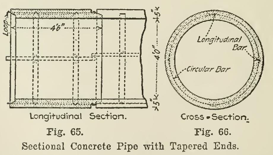
Reinforced Concrete Culvert Pipe. Plate 13 (A) illustrates the sectional concrete culvert pipe now being used in many cases instead of iron pipe. The sections are made 6 or 8 feet long so that they may be easily handled. The bell and spigot ends (Figs. 63 and 64) provide a good and flexible means of connection, but are expensive to construct; and tapered ends, as in Figs. 65 and 66, are more often used.
Table II shows the comparative weights and cost of concrete and cast-iron pipes from 1 ft. up to 4 ft. diameter; it is based on the price of $7 per cu. yd. for concrete, and cts. per lb. for cast-iron pipes. The thicknesses for con crete pipes of various diameters have been taken as approximately proportional to the thickness of cast-iron pipes of the same diameter, the 4-ft. pipes being used as a basis for calculation.

The first cost of concrete pipes at the place of manufacture would, according to the table, be less than of the cost of cast-iron pipes. The cost of transportation and of installing the concrete pipes would, on account of the greater weight and greater number of pieces, probably be very nearly double the cost for cast-iron pipes. On account of the lack of reliable data regarding this cost, it is very difficult to give a fair comparative estimate of the cost of the two styles of culverts in place. However, since transportation and installation of iron pipes is but a small proportion of the cost of the com pleted culverts, it is evident that the cost of a concrete pipe culvert in place would be but a small fraction of the cost of a cast-iron pipe culvert of the same diameter, provided the pipes were hauled only moderate distances.