Roof Framing
square, shown, rafter, line, building, feet and inches
ROOF FRAMING There is probably no part of a building in the construction of which the steel square will be found of greater direct usefulness, than the roof. In the framing of this most important part of the structure—on which the very life of the building, as well as the health and comfort of its inmates, will depend—there arise many prob lems of greater or less difficulty, which would be very difficult of solution were it not for the steel square.
11 shows a plan of a roof having twenty-six feet of span. The span of a roof is the distance over the wall plates meas uring from A to A, as shown in Fig. 11. It is also the extent of an arch between its abutments. There are two rafters shown in position in Fig. 11. The one on the left is at an inclination of quarter pitch, and marked 13, and the one on the right, marked C, has an inclination of one third pitch. These angles or inclinations rather, are called quarter and third pitch, respectively, because the height from level of wall plates to ridge of roof is one-quarter or one-third the width of building, as the case may be.

In Fig.12, the rafter B is shown drawn to a larger scale; you will notice that this rafter is for quarter pitch, and for convenience, it is supposed to consist of a piece of stuff 2 inches by 6 inches by 17 feet. That portion of the rafter that projects over the wall of the building, and forms the eave, is any width desired. The length of the projecting piece in this case is one foot— it may be more or less to suit the eave, but the line must continue from end to end of the rafter, as shown on the plan, and we will call this line our working line.

Laying out a Rafter.—We are now ready to lay out this rafter, and will proceed as follows: We adjust the fence on the square the same as for braces, press the fence firmly against the top edge of rafter, and place the figure 12 inches on the left hand side, and the figure 6 inches on the right-hand side, directly over the working line, as shown on the plan. Be very exact about getting the figures on the line, for the quality of the work depends much on this; when you are satisfied that you are right, screw your fence tight to the square. Commence on No. 1 on
the left, and mark off on the working line; then slide your square to No. 2, repeating the marking and continue the process until you have measured off thirteen spaces, the same as shown by the dotted lines in the drawing. The last line on the right-hand side will be the plumb cut of the rafter, and the exact length required, which will be found to be 14 feet 61 inches plus the projection given the eave. It will be noticed that the square has been applied to the timber thirteen times.
The reason for this is, that the building is twenty-six feet wide, the half of which is thirteen feet, the distance that one rafter is expected to reach, so, if the building was thirty feet wide, we should be obliged to apply the square fifteen times instead of thirteen: We may take it for granted, then, that in all cases where this method is employed to obtain the lengths and bevels, or cuts of rafters, we must apply the square half as many times as there are feet in the width of the building being covered. If the building to be covered is one-third pitch, all to be done is to take 12 inches on one side of the square and 8 inches on the other and operate as for quarter pitch.
We shall frequently meet with roofs much more acute than the ones shown, but it will be easy to see how they can be managed. For instance, where the rafters are at right-angles to each other, apply the square the same as for braces of equal runs, that is to say, keep the 12 mark on the blade, and the 12 mark on the tongue, on the working line. When the roof is more acute, or "steeper" than a right-angle, take a greater figure than twelve on one side of the square, and twelve on the other.
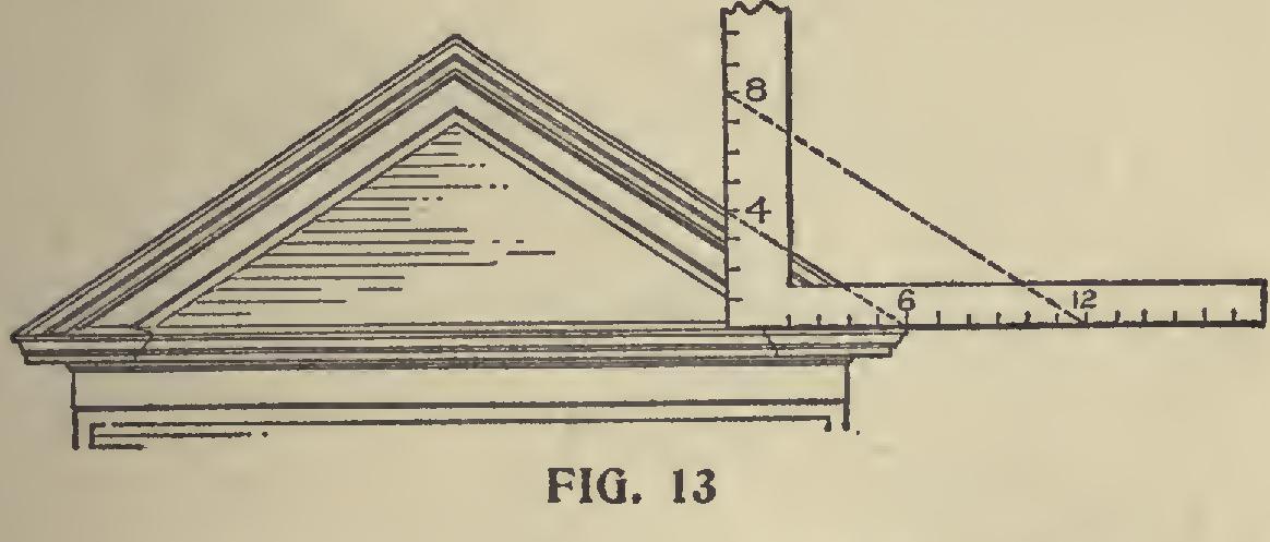
Whenever a drawing of a roof is to be followed, we can soon find out how to employ the square, by laying it on the drawing, as shown in Fig. 13. Of course, something depends on the scale to which the drawing is made. If any of the ordi nary fractions of an inch are used, the intelligent workman will have no difficulty in discovering what figures to make use of to get the "cuts" and lengths desired.