Private or Pneumatic Water Systems
system, tank, pump, tanks, pressure, desired and fig
PRIVATE OR PNEUMATIC WATER SYSTEMS Private or pneumatic water systems may be used in country and city homes, factories, large buildings, etc., where there is no city water system; where the city water-supply is inade quate for fire protection in factories and other buildings, for water supply for small towns or villages; and in fact for almost any condition that may arise, requiring a system of water supply.
Fig. 94 illustrates a combination that will meet the requirements of the average small installation. The principal parts of this com bination are a tank and a hand force-pump. The tank is supplied with a water gauge to show the height of water. The action of the outfit is as follows: After the connections are made as shown in the figure, the pump is operated to fill the tank. The water, entering the bottom of the tank, compresses the air in the upper portion, and gives the necessary pressure to deliver the water to the points desired through the pipe marked "supply to House." The gauge registers the pressure in the system. The amount of pump ing to be done will depend, of course, on the quantity of water used, and for the average dwelling, a few minutes pumping every two or three days, will be sufficient to keep the system ready to respond to any demands made upon it for water.
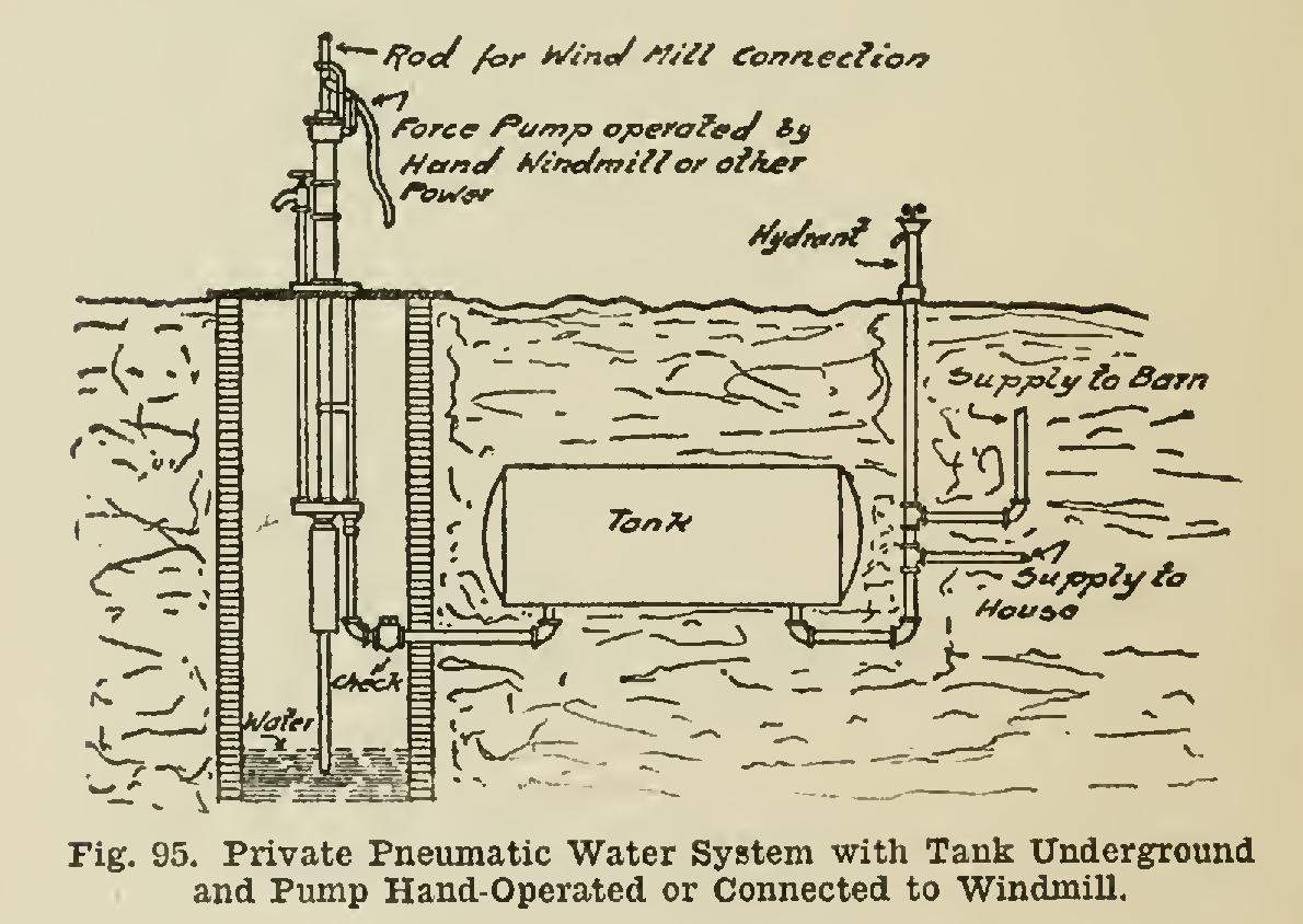
If desired, power may be used, derived from a windmill, gas, gasoline, or hot-air engine, or electric motor, either in conjunction with the hand force-pump or not, as preferred. The "Leader" combinations may be fitted up to fill practically any and all requirements. A check valve should always be placed in the discharge pipe from the pump to the tank, to retain the pressure in the tank when the pump is not in operation.

Fig. 94 shows the tank placed in the base ment of the building.
Fig. 95 shows a combination where the tank is buried in the yard, and the pump may be operated by hand, or attached to a windmill, as desired.
This form of water system is the favorite for country homes and farms. The use of the tank as shown does away with the old method of placing the tank in the air on a plat form, or in the attic of the house or upper portion of the barn, and gives a water pressure that would not ordinarily be obtained by the 1 latter methods; and it also eliminates the freez ing feature that usually accompanies the latter.
With a pneumatic system, you practically have the same benefits that you would enjoy with the city water system.
Fig. 96 illustrates a water-works system which will fill the requirements for a small town or village of from 600 to 1,200 population, fur nishing a water-supply for fire protection, domestic use, etc. This illustrates 3 tanks, 6 feet in diameter, 24 feet long, with a total capacity, in the three tanks, of 15,180 gallons; and the tanks may carry a working pressure of 100 pounds to the square inch. The pump has a daily capacity of 120,000 gallons, when pump ing from a well where the water is not over 150 feet below the level of the pump. The pump is operated by an 8-horse-power gasoline engine arranged to cut off automatically by the water pressure. This feature reduces the cost of operating to a minimum. This system can be increased or diminished to suit local conditions, and furnishes a thoroughly up-to-date water works system. The illustration shows the various parts of the system.
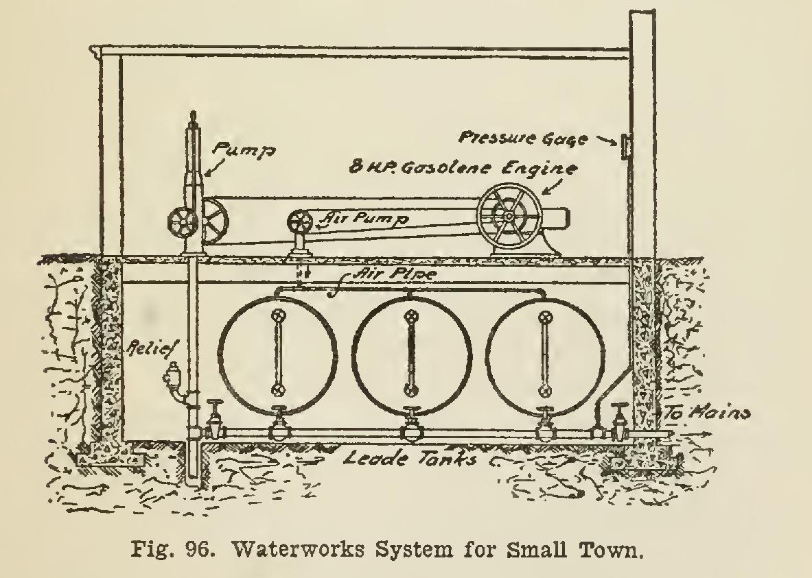
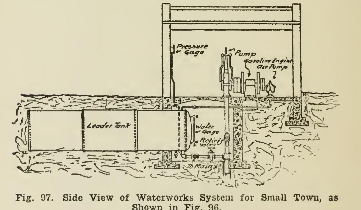
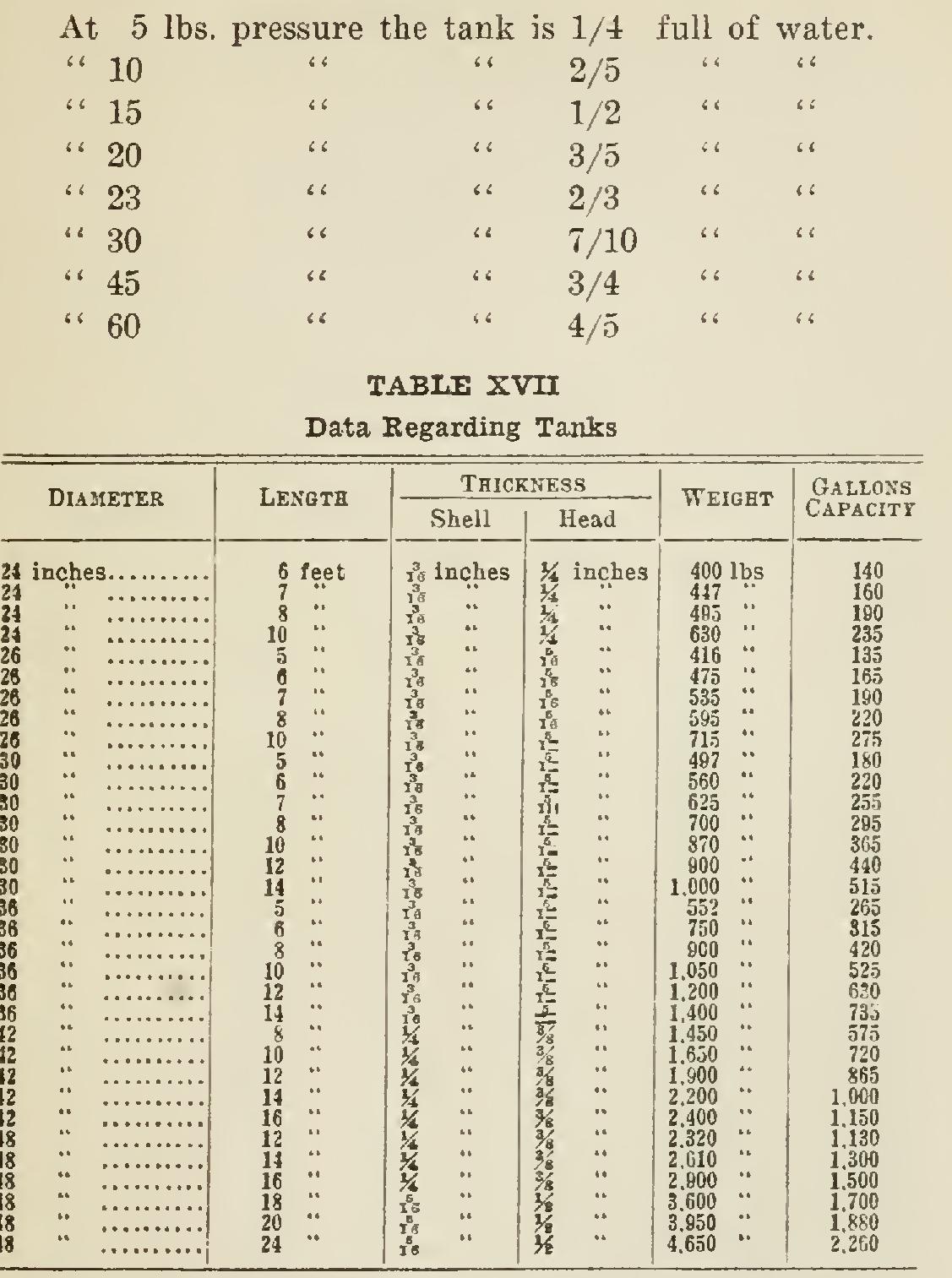
Fig. 97 is a side view of the system shown in Fig. 96, and illustrates the manner in which the tanks may be buried in the ground, which will afford protection against freezing and will also lesson the cost of installation. The tanks may be placed above-ground if desired; and there is practically no limit to the combinations that can be made to suit local conditions or re quirements. The following will give some useful information regarding the tanks: Amount of Water in Tanks at Various Pressures The above table gives a list of the common sizes; but tanks are built to other special sizes if desired.
It can be clearly seen, that the more water you force into the tank, the more the air in the upper portion of the tank will be compressed, and the greater will be the pressure in the water system. This is a simple explanation of how the pressure is created to force the water through the piping to the desired points.