Vacuum and Vapor Heating
air, system, return, fig, water, steam, radiator and boiler
The Trane system involves the use of a cup of mercury in the center of a device called a mercury seal, as illustrated by Fig. 97. A special form of automatic air-valve, having a union drip connection, is used on the return end of each radiator. An air-pipe connecting to this valve is carried to the basement, where it is joined into a larger air-pipe called an air-main. This line follows closely the direction of the steam main, terminating at a point near to the boiler, where it drops down and connects to the top of the mercury-seal device. A slight pressure will force the air out of the seal through the mercury, which will, however, by reason of its greater density, effectively prevent the return of the air into the air-line, by this operation placing the system under a vacuum.


The K-M-C system also makes use of a mercury device, Fig. 98, in quite the same manner as the Trane. In connection with its usage, however, some special appliances are necessary. A small device, called a retainer valve (shown in Fig. 99), when placed on the return end of the radiator, is designed to prevent the steam from entering the air-line. Should any supply find its way into this air pipe, it is taken to a small tank, called an accumulating tank, into which the air-line con nects. As this tank is partially filled with water, it assists in condensing the steam; and from the accumulating tank, the air passes through floating check-valves before entering the mercury seal. Fig. 100 shows the method of connecting the tank, and also illustrates the floating check-valves; while Fig. 101 shows the arrangement of the piping and fixtures at the boiler.
The other systems of vapor and vacuum heating require the use of ejectors, air-traps, etc.
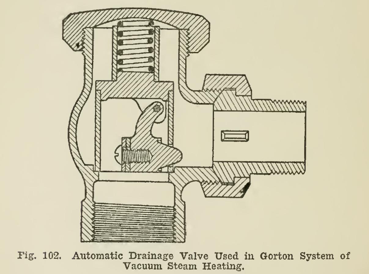
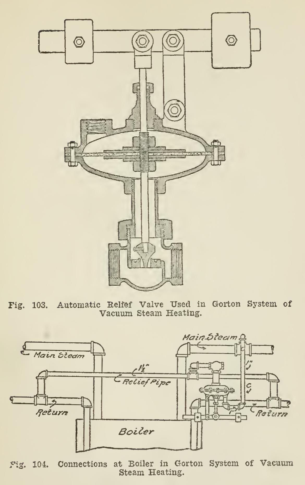
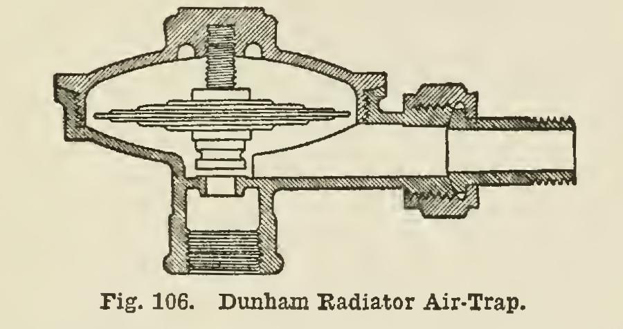
The Gorton arrangement is a vapor system involving heating below atmospheric pressure. In its application, the two-pipe method of piping is employed. A drainage valve, Fig. 102, is used ou the return end of each radiator, in operation being so sensitive that a very slight pressure will open it a sufficient distance to allow the air and the water of condensation to pass into the returns. Connected to the system in the base ment, is an automatic relief valve, as shown in Fig. 103. This valve is operated by the differ ence in pressure between that of the steam and of the return pipes, remaining closed until the accumulation of air in the return mains increases the pressure, when it will open sufficiently to relieve the air, closing again after the release of the surplus. The arrangement of the connec
tions at the boiler is shown in Fig. 104.
The Ryan system involves the use of air lines similar to those of the K-M-C and Trane systems. With it the air is exhausted to the atmosphere through an air-trap. A small steam pipe connected directly to the trap from the boiler, acts as an exhauster in creating the vacuum pull upon the air-line.
The Moline system is styled the Vacuo Vapor Method, and in the method of piping is quite similar to other vacuum systems—that is, in so far as the steam supply and air-line are concerned. The air and steam in the air-line are taken to a condensing radiator; and an ejector placed between the supply valve and the radiator creates the necessary pull on this air main. Fig. 105 illustrates the system clearly.

Note that from the condensing radiator, the air enters an air-trap which permits it to escape, but which closes against the flow of steam and water. The air from the trap is discharged through a vacuum valve having a perforated bottom and placed in a copper receptacle half filled with water, which results in sealing the system against the return of the air. In dis charging to the atmosphere, the escaping air bubbles up through the water in the receptacle.
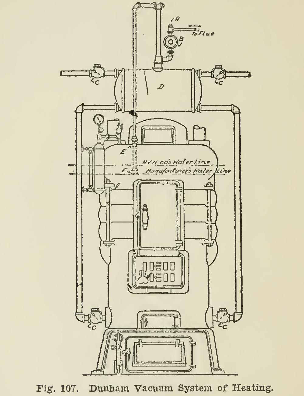
The Dunham plan calls for the use of a sys tem of flow and return piping without the addition of air-valves. On the return end of each radiator is placed an appliance called a radiator air-trap, as illustrated in Fig. 106, the device possessing the attributes and action of a thermostat. It is open to allow all air and water to escape from the radiator, closing against any escape of the steam. The water and air are taken through the return to a re ceiving tank located above the boiler, the supply of the latter leaving the system through a vacuum valve and passing to the atmosphere, the water entering the boiler through the return. Fig. 107 shows the application of this system. Condensation passes to the receiving tank only after its heat has all been given up. Here it accumulates until such a quantity of water has been evaporated from the boiler as will lower the water-line sufficiently to uncover the end of the equalizing tube F, which connects through the boiler coupling E, forming a loop over and down into receiving tank D.