Boiler Accessories Valves
valve and pressure
Check-Valves. When it is necessary that the flow should always take place in the same direction, as in the feed-pipe of a boiler, checkvalves are used. There are several forms shown in Fig. 40, one of which has a similar pattern to a globe valve, with a ball or flat valve, the seat being parallel to the direction of flow. The valve is held in place by its own weight, and by the pressure of the fluid in case of a reverse flow. In the swinging cheek-valve, the sent is at an angle of about 45 degrees to the direction of flow. It is fitted somewhat loosely where it is fastened to the swinging arm, so that it may properly seat itself. This form is usually preferred, as it offers less resistance to flow and there is less chance for impurities to lodge on the valve-seat. When a check-valve is used in the boiler-feed pipe, there should be a between it and the boiler, which can be shut in case the check-valve should get out of order.

Materials. For pressures under 200 lbs. per square inch, cast iron may be used for the body of the valve; but, for economy, it should be used only when the pressure is over 130 lbs. For heavy work it is frequently necessary to have a massive valve that cannot easily be broken. In such a case a cast-iron body is the most suitable thing. The valve-seat, valves, spindles, stuffing-box, glands, and nuts are usually made of gun-metal or brass. For very high pressures, especially on steam mains, cast steel is generally used, with gun-metal fittings similar to those enumerated for the cast-iron valves.
Safety-Valves. Safety-valves are used for reducing the pressure in the boiler when it exceeds a certain limit, and to give warning of high pressure. There are several different types, but the essential features are a valve opening upward, held on its seat by a weight or spring. When the pressure in the boiler exerts a force greater than that holding down the valve, the valve will open automatically.
The lever safety-valve shown in Fig. 41 is the most common type for stationary work, especially for small boilers. The valve is held in place by a weight at the end of a lever. The force required to lift the valve is governed by the location of the weight on the lever-arm.
The body of the valve is usually made of cast iron, the seat being of brass. An opening on the side of the valve may be connected with the feed-water heater or drain, if the escape of steam into the air is undesirable. If the valve becomes leaky, it should be reground; but no attempt should be made to make it tight by increasing or moving the weight on the lever.
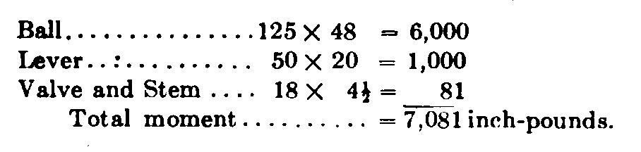
The amount of necessary weight on the lever, and its distance from the fulcrum, can be determined in the usual manner of computing leverage forces and moments, remembering that weight times weight-arm is equal to power times power-arm. In such a valve as this, power is the steam pressure, and the power-arm is the distance of the center of the valve from the fulcrum. There are four weights acting downward—the ball, the lever-arm, the valve, and the spindle—and in the process of computation the weight and leverage of each must be taken into account.
Suppose, for example, that we have a lever safety-valve such as is illustrated in outline in Fig. 42, and that we know the following conditions: the ball weighs 125 lbs., and is suspended at the end of the lever 48 inches from the fulcrum; the valve and valve spindle together weigh 18 lbs., and are 4-1/2 inches from the fulcrum; the lever-arm itself weighs 50 lbs. If the valve-seat is 5 inches in diameter, at what pressure will the valve blow off, ignoring the friction of the stuffingbox and fulcrum pivot? The center of gravity of the lever-arm must be determined from the drawing (Fig. 42), and this is found to be 20 inches from the fulcrum The leverage of the weights acting downwards is then as follows: Now, if the valve-seat diameter is 5 inches, the area of the valve will be (pi*D*D)/4 = (3.1416 x 25)/4 = 19.63 sq. in. The total moment to be overcome is 7,081 inch-pounds, and its distance from the fulcrum is 4-1/2 inches. Therefore the necessary upward pressure on the valve will be 7,081/4.5 = 1,573.5 lbs. If the area ofthe valve is 19.63 sq. in., then the necessary pressure in pounds per square inch would be 1,573.5/19.63 = 80 lbs., .approximately. That is, this safetyvalve would blow off when the boiler pressure reached 80 lbs. per square inch.
If it is desired to design a valve that will blow off at known pressure, the same principles will apply, but the computations will be figured in the reverse order. The area of the valve, times the boiler pressure, would give the total lifting force; and this, multiplied by its leverage, would give the lifting moment, which would be resisted by the downward moment of the combined weights of valve, valve-stem, lever, and ball. If the moments of the lever, valve, and valve-stem were known, the rest, of course, would be made up by the ball: If the length of the lever-arm were known, then the weight of the ball would be varied to correspond; and, conversely, if the weight of the ball were fixed, the length of the lever must be made to correspond.