Boiler Accessories Valves
valve and steam
The lever safety-valve has several defects. It does not close promptly when the pressure is reduced ; and it is likely to leak after it is closed, and may readily be overloaded, or even wedged on its seat. It is essential that a. safety-valve should be automatic, certain in its action, and prompt in opening and closing at the required pressure. It must be one that can be relied upon under all circumstances.
The pop safety-valve fulfils the above requirements better than those of the lever type. Pop valves open when the steam pressure is sufficient to overcome the tension of the spring. Fig. 43 shows a "Crosby" pop safety-valve for stationary service. T h e valve C is connected by the flange B to the central spindle A, and is held down on its seat by the pressure of the spring S. The valve C is provided with wing guides and an annular lip E. The guides fit smoothly into the seating D, upon which the valve rests. The seats of the valve have an angle of 45 degrees. The under face of the lip E, together with the seating, forms a small chamber through which all the steam must pass to the open air. A number of small holes drilled vertically through the flange F, connect with the chamber and allow part of the steam to escape. The action of the valve is regulated by the screw ring G, which allows more or less steam to escape through the holes in the flange F. Raising the screw diminishes, and lowering it increases, the area of the holes. If the loss of steam is too great when the valve blows, turn the screw ring down.
Safety-valves should be connected directly to the boiler without any pipe or elbow. They should be tried every day by means of the lever.
The valve shown in Fig. 44 for stationary boilers, is made by the Ashton Valve Company. The general principles are those of all pop safety-valves. The valve-seat is made of composition or nickel, and with a bevel of 45 degrees, as is the United States Government standard. The pop chamber is surrounded by a knife-edge lip, which wears down in proportion with the seat, thus keeping the outlet of the same relative proportions, giving a constant amount of pop.
The amount of pop—that is, the difference of pressure between the opening and the closing of the valve—is regulated from the outside by means of the screw-plug pop regulator shown at II in Fig. 44. If more pop is desired, turn the regulator so that S will be more nearly perpendicular. To lessen pop, make 0 more nearly perpendicular. The springs are made of Jessop's best steel.

The inlet and outlet arc both on the same casting, so that the valve may be taken apart to be cleaned or repaired, without disturbing the boiler connection. It has a lock-up attachment, so that the regulating parts cannot be tampered with, either by accident or by design The spring is encased, thus protecting it from the steam.
The "Star Marine" pop safety-valve is shown in Fig. 45. It has a bevel seat, and is provided with a cam lever by which it may be raised from its seat when there is no steam pressure. The outlet of the valve, if desired, may be piped to the supply tank or to any other point.
Safety-valves for locomotive boilers must be made of heavy material to stand the severe usage. They should be so constructed that they will not cock or tilt. The "Ashton" valve shown in Fig. 46 is constructed so that the amount of pop can be regulated by merely turning the two posts marked 2 and 3 to the right or left. The noise of the steam escaping from the ordinary safety-valve is disagreeable, and in some States the law requires the use of the muffler safety-valve. The Ashton valve shown in Fig. 46 has a top muffler.
Reducing Valves. Sometimes steam is desired at a lower pressure than that of the boiler. For instance, a small low-pressure engine may be run by steam taken from the same boiler that supplies a higher-pressure engine. This reduction is accomplished by throttling the steam by means of reducing valves. These are arranged to be operated automatically so that the pressure can be reduced and a constant pressure in the steam pipes maintained. There are several forms in general use.
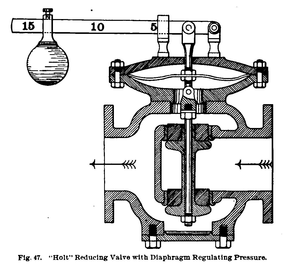
In the "Holt" valve, Fig. 47, the low-pressure steam acts on the lower side of the diaphragm; and the weight, which may be set so as to cause the desired pressure, acts on the other. The movement of this diaphragm causes a balanced valve to move to or from its seat. The valve opens until the steam pressure equals the weight above. The pressure in the main steam pipe does not affect the movement of the valve. It depends only upon the pressure on the two sides of the diaphragm.
Another form, the "Mason," is shown in Fig. 48. A spring, which may have its tension altered by a key, takes the place of the lever and weight in the Holt valve. When the pressure in the low-pressure system has risen to the required 'point, which is determined by the spring, the valve closes, and no more steam is admitted until the pressure falls sufficiently to open the valve again.
In another form, a piston acted on by the low-pressure steam regulates the opening of a balanced valve, and this maintains a constant steam pressure.
In the "Foster" reducing valve, the valve is held open by the spring and levers, until the steam pressure at exit presses on the diaphragm sufficiently to close the valve. The valve is held open so as to admit just the proper amount of steam to maintain the required pressure.
When a reducing valve is used, a stop-valve should he put in to prevent flow:when steam is not in use.