Pictorial Drawing 110
isometric, lines, drawn, equal, located, vertical and parallel
117. Simple rectangular objects, as those of Figs. 83, 84, and 85, can usually be drawn at once from given dimensions without reference to plan or elevation. In more complicated cases, however, the plan and elevation are generally desirable, and often they are necessary.
118. Non-Isometric Lines. Non-isometric lines are those which cannot be shown parallel to the isometric axes. This classification em braces oblique straight lines and also curves.
An oblique line may be located in isometric drawing, by fixing the position of the ends of the line by co-ordinates; and the isometric of a curve is made by locating a sufficient number of its points in isometric by means of co-ordi nates, and then drawing a smooth curve through these points.
119. Fig. 86 shows plan and elevation of a prismatic block with two faces cut off obliquely. To construct the isometric, let d be taken as the lowest corner of the isometric, and located at d'. The base may readily be drawn with the edges as 30-degree lines. The lines and are oblique, and cannot be drawn in isometric at the same angle. Point c may be located at once, since is a vertical line. Point b is located in projection by means of the horizontal distance and the vertical height These lines will show parallel to the isomet ric axes, and may be laid off in their true lengths. " Hence, from d', lay off equal to d°-b', and erect the vertical line equal to thus locating point b'.

The point is determined in a similar way by means of the co-ordinates equal to and equal to The left-hand side may then be completed. Next the 30-degree edges from al, b', c", and are made equal to the thickness, and the edges of the back then drawn in and the isometric completed.
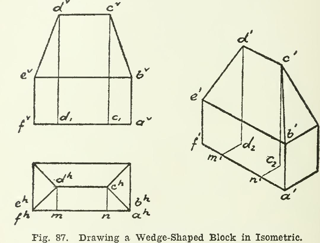
120. To draw a wedge-shaped block in iso metric, refer to Fig. 87. The base is drawn in isometric as before, and the vertical edges may be &awn immediately, obtaining points etc. The point is located in isometric by means of three co-ordinates or distances, taken from the projection. First, the horizontal dis tance ah-n, laid off at second, another hori zontal distance ch-n drawn at and third, the vertical height laid off at The point cl is thus fixed in position by the three co-ordinates parallel to the isometric axes. The
rest of the figure may then be easily finished.
121. Isometric of Curved Lines. Points in the isometric of circles or other curved lines, are also determined by means of cc-ordinates parallel to the isometric axes.
122. A cube having one circle traced on the top and another on the front, is given in Fig. 88. Taking 0 at 0', the isometric of the cube is drawn. The circles will then be constructed in the top and the left front side.

Taking first the smaller circle in the top, divide it into any number of equal parts, as eight in the figure. The points might be located by means of co-ordinates from the front edge a-b of the square; but it is better to refer them to the horizontal center line of the circle (8-1), which, when produced, is the diameter m-n of the square. Next draw the other diameter of the square passing through 4-5. The two diam eters are drawn in the isometric, and points 1 and 8 are located on by laying off and equal to the radius, and points 4' and 5' are then found on the other diameter at the same distance from the center dl.
In the plan, lines 2-3 and 6-7 are parallel to the diameter 4-5, and will be shown parallel to in isometric. From the center mark off on ml-nl the distances and equal respectively to d-e and d-f; draw 2'-3' and 6'-7'; and lay off both ways from el the distance e-2, thus fixing 2' and 3'. The same distance is laid off from fl, locating 6' and 7'.
The ellipse, which is the isometric of the circle, is then drawn through the points. The axes of the ellipse will lie on the diagonals of the isometric square.
The larger circle in the vertical face of the cube is similarly constructed, using the hori zontal diameter p-r and the ordinates as shown in the figure. The axes of this ellipse will like wise lie on the diagonals of the face of the cube.
123. Isometric of a Vertical Cylinder. The plan of the cylinder is shown at A, Fig. 89. The first step is to circumscribe a square about the circle, with the sides respectively parallel and perpendicular to a T-square line. As this is a plan of the cylinder, the sides of the square will be 30-degree lines in isometric.