Pictorial Drawing 110
shown, oblique, line, projection, drawn, isometric and lines
Let 0 be placed at 0', and the isometric square drawn. The circle of the base is then drawn as in the preceding case. From each point in the base, vertical lines are drawn equal to the desired length of the cylinder, thus locat ing points on the circle of the upper end. The two vertical lines on the outside will be tan gent to the bases, and will form part of the outline.
124. Isometric of a Cone. Let it be required to draw a right circular cone with its axis hori zontal. If the axis is horizontal, the base will be vertical. Hence, draw an elevation of the base at A, Fig. 90, and circumscribe a square. Let 0 be placed at 0' and taken as the lowest corner of the isometric. As A is an elevation, two sides of the square are vertical lines, and must be so drawn in the isometric. The iso metric circle is then drawn as before, using the diameters of the square and the given co-ordi nates.
A line drawn from the center of the base at 30 degrees to the left, will represent the axis, which is perpendicular to the plane of the base. On this axis the desired altitude of the cone is laid off, locating the apex b'. Lines drawn from b' tangent to the base, complete the view of the cone.

NOTE—Although only eight points have been used for the circles in the given figure, for larger figures or for more accurate results more points would be necessary.
125. The isometric of a wooden bracket is shown at B in Fig. 91. At A are drawn two views—the front elevation, and the left side elevation giving the thickness. The isometric is constructed as shown in the figure.
Oblique Projection 126. Oblique projection differs from isomet ric drawing in that one face of an object is usually represented in its true size and shape as if parallel to the plane of the drawing, while the edges perpendicular to this face are drawn at any convenient angle, as 30, 45, or 60 degrees, either to the right or left.
In Fig. 92 are shown the three angles of inclination for the case of a cube.
Cavalier or cabinet projection is the term applied to oblique projection when the 45-degree inclination is used.

The lines in oblique projection correspond ing to the isometric axes, are as shown in Fig. 93, one vertical, one horizontal, and one oblique (in this figure 45 degrees). Any line or edge which can be drawn in oblique projection paral lel to the 45-degree line, will be shown in its true length.

This system of representation is perhaps a trifle simpler than isometric, since not only all lines parallel to o-a or o-b are shown in their true lengths, but also all lines parallel to the plane of o-a and o-b.
On account of this property, an oblique pro jection is often more easily made than an iso metric—as, for instance, in the case of circles or curves which lie in a plane parallel to the plane of the drawing. Lines which are neither parallel nor perpendicular to the plane of the front face of the object, must be located by means of properly chosen co-ordinates, as in the case of isometric.
127. Two pieces of joist with the ends cut for halving together, are shown in Fig. 94. All of the edges are either parallel or perpendicular to the plane of the front face, and are therefore shown true length.
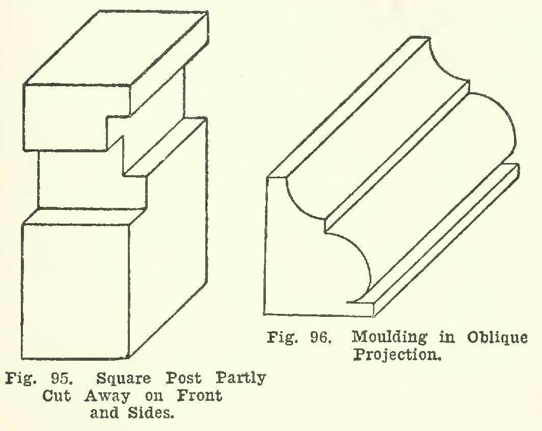
128. Fig. 95 shows a square post, with parts cut away on the front and side.
129. A short piece of moulding is repre sented by oblique projection in Fig. 96. The curves of both the front end and the back end, are shown in their true size and shape. From such a drawing, a plan and elevation might readily be constructed.
130. An arch with a skew face is shown in plan and elevation in Fig. 97. This case will illustrate the use of co-ordinates in the con struction of the oblique projection. As the front face of the arch which is projected in the line ah-zh is not horizontal, it will not be shown true size in the oblique projection, and the various points must be determined by co-ordinates. First draw through zh a horizontal line, and produce ahbh to meet it at oh, and take the posi tion of oh at o' for the oblique projection. Then o'z' represents ohzh.
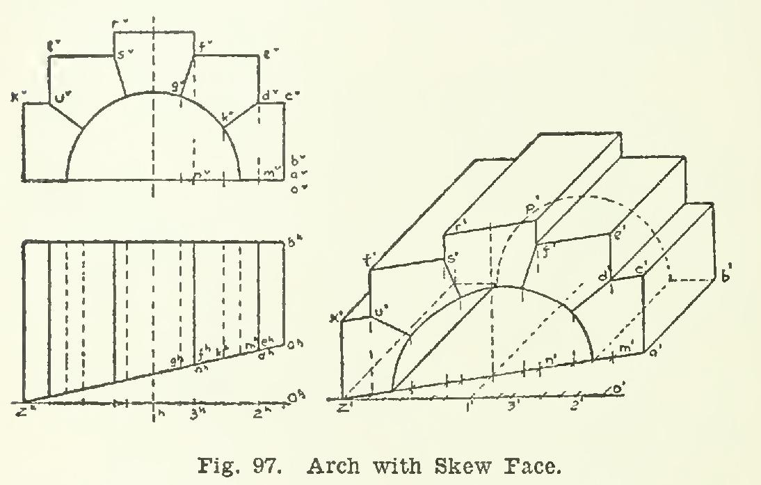
Next, a' is located on the 45-degree line through 0', at a distance equal to °bah. The line joining a' with z' is the base line of the face of the arch.
To locate the front faces of the arch stones, proceed as follows: Point c' may be found immediately by making the vertical line a'-c' equal to avcv, and a vertical through z' of the same length will give one corner of the left hand stone. It is desirable to locate the remain ing corners with reference to the center line through 1', since the points are symmetrically located on either side.