Projection 49
elevation, shown, view, true, seen, base and plane
Next, for the elevation or front view of the cube, the paper must be considered as the V plane, and the GL as H seen edgewise. Then, as the cube is below the H plane, its projection on V will be below H as seen edgewise—that is, below GL. This elevation of the cube will be a square Av, vertically below A'. The cor ners of the cube may be numbered, calling the four upper corners 1, 2, 3, 4, and the four lower ones 5, 6, 7, 8. The two projections A° and A' are squares of equal size, which is evidently as it should be, since each face of the cube is of the same size, and each view is taken at right angles with the face.
53. The Co-ordinate Planes Seen Edgewise. The GL sometimes represents H, seen edgewise, and sometimes V seen edgewise. When con sidering a plan or top view, GL is V seen edge wise; but when regarding an elevation, GL is H seen edgewise.
Examples. In Fig. 45, six simple objects are shown, all in the first angle. Reading from left to right these are: Square prism; round bar or cylinder; the same with a square hole from one end to the other; the same cylinder again, but with a small block placed on the upper end; a circular cone standing on H; and a short joist with a tenon on the front end.
Fig. 46 shows the elevation and plan of a common hexagonal nut. The double dotted lines of the elevation, and the two inner circles of the plan, indicate that the nut is threaded.

Notice that the thickness or height of the nut is shown on the elevation; while the true distance between the parallel faces is given only in the plan. Each side of the nut is shown in its real width on the plan; but on the elevation, of the three front sides A, B, and C, B alone is shown in the full width, A and C appearing very much narrower. This illustrates several very important principles of projection, which may be stated thus: 54. (a) If any flat surface is parallel to H or V, it will be drawn on that plane in its real size and shape; but if a surface is oblique to H or V, its projection or view on that plane is less than the true size, and does not show the exact shape.
Observe that although the face A, for exam ple, is oblique to the V plane, it does not follow that all its dimensions are oblique. The height of the face A is not affected by the inclination of the surface with the vertical, and hence is shown in its true length in the elevation.
55. (b) If any edge of a solid, or any single line, is parallel to either H or V, it will be shown on that plane in its true length.
These principles are still'further illustrated. in Figs. 47, 48, and 49. Fig. 47 shows a square prism placed with its length vertical. Notice the numbering of the top and bottom. Why are some of the faces in elevation shown in their true size? Only one dotted edge appears. (A dotted edge in any projection is understood to mean an edge which is not visible in that view.) 56. In Fig. 48, a regular hexagonal pyramid is given standing on its base, and with its axis ab perpendicular to H. This solid has six sloping surfaces and one base. Of these seven faces, the base alone appears in its true size.
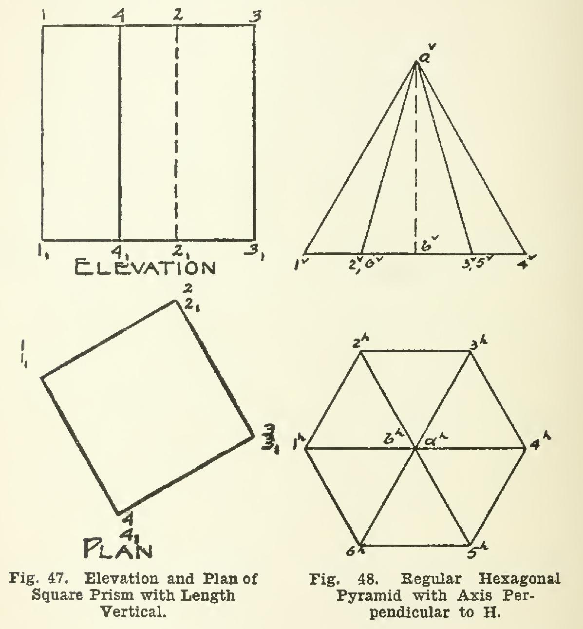
Two of the inclined edges, a-1 and a-4, are shown in their true lengths in elevation at a7-1` and av-4", since the lines in space are parallel to the vertical plane.
57. Fig. 49 is precisely the same object as in Fig. 48, hilt placed in a different position.
In this position, the base is parallel to V, the axis, a-b perpendicular to H, and the apex away from the draftsman. Note the dotted lines in the elevation, the only visible part of the solid in elevation being the base. The edges a-1 and a-4 are now parallel to the horizontal; hence their true lengths are ah-1' and The base 1-2-3-4-5-6 is parallel to V; hence perpen dicular to H; and its H projection is the straight line 1'-2". . .4'. The base in the preceding figure is perpendicular to V, and its V projection is the straight line 1°-2°. . .4°.
The statement of the principle involved is as follows: 58. If a surface is perpendicular to H or V, it will be seen edgewise in that view, hence will appear simply as one line.
59, In these three figures on the prism and pyramid, it may readily be seen that it would be impracticable to draw first the view showing the side faces. For example, in Fig. 47, the widths of the surfaces in elevation are not known until the plan is drawn. Hence, to draw a prism, or pyramid, or other object of a similar character, draw the base or the end view first.
This direction applies with equal force in other cases of a more practical nature—for example, the slope of a roof is shown at its true angle in an end view.