Structural Drafting 148
angles, rivets, shown, drawing, notes, distance, spaces and rivet
Besides the general distinction between shop-driven and field-driven rivets, other differ ences are made in the drawing to denote the kind of The conventional manner of indicating the kind of head to be made on a rivet is shown in Figs. 158 and 159, which are according to the standard of the American Bridge Company.

It will be seen that the distinguishing feature for field riveting is the small blackened circle, while all of the different heads for the shop rivets are left light. A small inner circle invariably stands for at least one countersunk head. On the side or end view of a structural shape, if the rivet is to be driven in the field, the rivet-hole is shown black, as in Fig. 160.
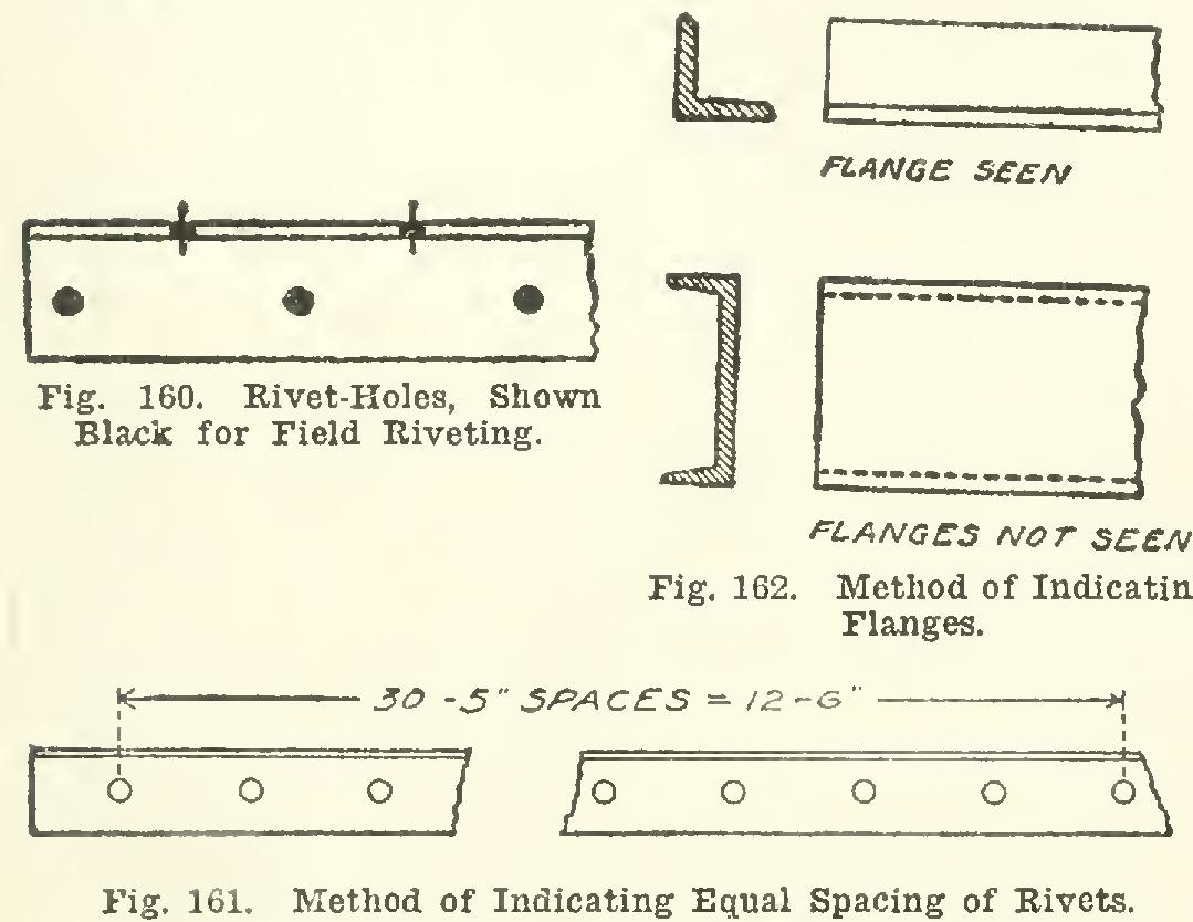
When a line of rivets is to be located with equal spaces between, it is better to express the spacing as in Fig. 161, rather than to repeat many times the same dimension. In case the total distance does not divide evenly by the number of spaces, the total distance may be given, and also the. number of equal spaces required.
When the side view of an angle or channel is shown, the flange is represented by two paral lel lines—both full, if the flange is on the near side; and one or more dotted, if the back of the shape is shown (see Fig. 162). A similar practice obtains if the other shapes are shown.
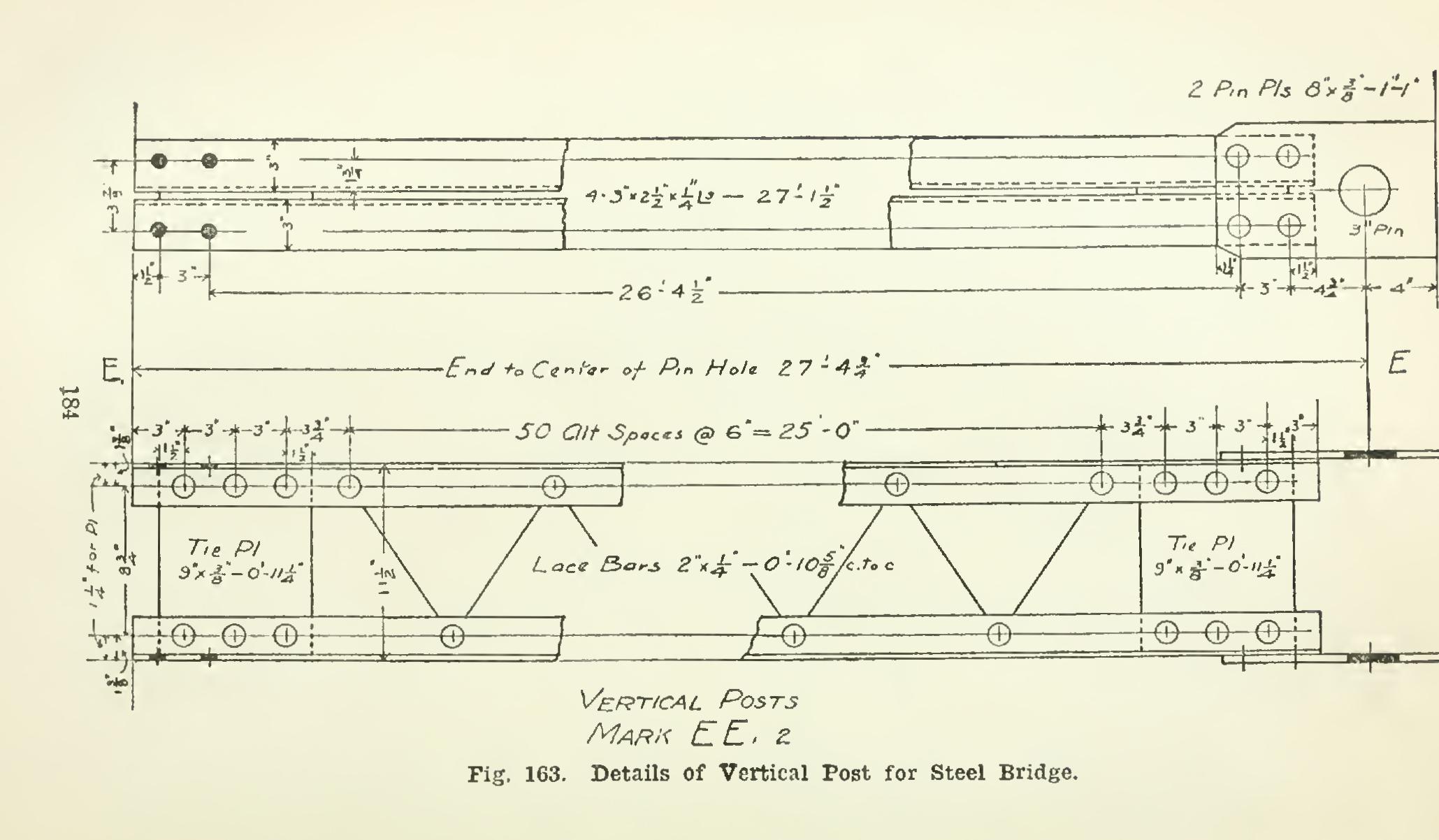
Details of a Vertical Post. Fig. 163, from a drawing of the Pittsburg Bridge Company, is the plan and elevation of a vertical post for a steel bridge. The post is made up of four angles laced together. The angles are fastened together at the ends by tie-plates, which, like the lacing bars, pass between the angles and are riveted to them. On the plan (the upper figure), the number (4) of angles used is given, together with the size, 3 in. by in. by 1/4 in.; the symbol for angles is used, instead of the written word; and the total length of the angles is given. The hole for the 3-inch pin is located from each end of the pin-plates; and its distance from the further end of the angles is also shown.
The expression "50 Alt. 6" 25'-0",",lettered just above the elevation, means that fifty alternate spaces between rivets, each space equal to six inches, amounts to a total distance of twenty-five feet between the first and last rivets of the series. The term alternate spaces means that each 6-inch space is the dis tance that any rivet in one row is in advance of the nearest rivet in the other row. The distance, therefore, between any two consecu tive rivets in the same row is 12 inches. Notice
that the lacing bars are indicated merely by the center lines, and that the length as given is from center to center.
This drawing illustrates actual drafting room practice, such as the customary method of representing the angles, the manner of locating the rivet centers, the giving of the over all length of the angles, and also the distinction between the shop- and the field-driven rivets. According to the drawing, all of the rivets are to have full heads, both sides (see Figs. 158 and 159).
Architectural Drafting It would be a commonplace to insist on the advantage to all property owners and to all classes of workers engaged in building construc tion, of a knowledge of the principles of archi tectural design. It is equally important that they should know how to read and interpret intelligently the working drawings that are the guides to the details of actual construction, and, if need be, to make these drawings themselves.
The first impression given by a set of draw ings applies as well in Architecture as in any other hue of work. So often we hear it said, "It certainly makes a good impression." Apply ing this same principle to architecture, let us consider a few general requirements in order to finish a set of plans in Ale best manner, and also have them appeal to a person not familiar with architectural work.
The drawings should be complete in every respect. They should be fully dimensioned with plain figures; all material plainly marked by arrows; each room named, for the sake of reference; and the various parts of the work 187 carefully explained by explanatory notes. Make these notes clear, concise, and with no mistaking the part to which they refer. While the title of each page may be lettered in a more elaborate letter, make all explanatory notes plainly let tered. Drawings in general have but few notes of explanation. Make it a rule to explain fully all the questionable portions of a building. This applies to the plans, as well as the eleva tions, sections, and details. In the arrange ment of notes, if there are those that do not refer to any particular portion of the drawing, place these notes over the sheet, to make it well balanced. Do not try to crowd them into one corner of the sheet or along one edge. Place them where they will make the drawing as a whole look the best.