Simple Morris Chair Design
inches, lines, gauge, set, inch, one-quarter, legs and pieces
The legs of the chair, Fig. 59, may be cut to length. Four pieces each twenty-five inches long are needed. If these pieces are mill-planed to the correct width and thickness, and have their surfaces square one with another, all that remains is to remove the mill marks with smooth plane and scraper, and square one end of each piece properly. The other ends need not be squared now, for they are to be cut to slope after the frame has been put together.

Place the four pieces side by side, with the face marks upward; and even the squared ends in the usual way. Begin at the squared ends, and measure off consecutively, and square sharp pencil lines across at one inch, seven inches, four and one-quarter inches, four inches, and then eight and three-quarter inches. Separate the legs, and, with the knife and square, carry the lines which shall mark the shoulders of the tenon at the end of the legs entirely around the pieces. The other lines should be carried across the other face marked X X only, and a sharp pencil should be used. To determine upon which face the hole for the dowel is to be bored, it is wise to set up the legs in the positions they are to occupy relative one to another and mark their location in some way. The X X faces are to be turned in in doing this.
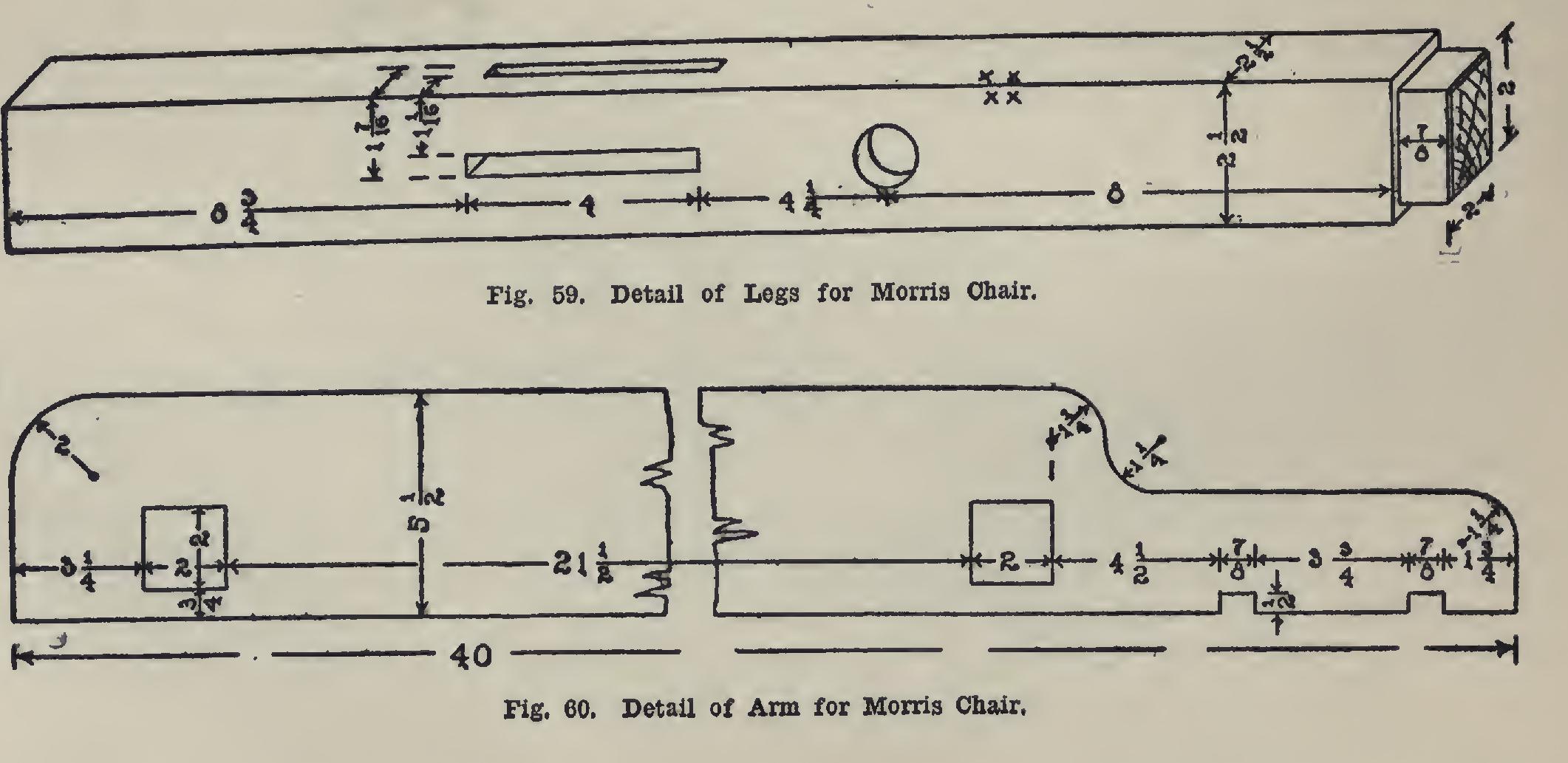
The next step is the gauging. For the tenon, set the gauge to one-quarter of an inch, and gauge on ends and on the sides as far as the shoulder marks, gauging from the X X sides. After all have been gauged for this setting, reset to two and one-quarter inches, and repeat.
For these mortises, set the gauge first to one and one-sixteenth inches, and gauge all the mor tises from the X X sides; then reset to one and seven-sixteenths inches, and repeat.
To locate the center of the holes for the rod, set the gauge to half the thickness of the leg, one and one-quarter inches, and gauge a line across the proper pencil lines.
nip the tenon; then crosscut the shoulders. Bore the holes in the legs with a one-inch bit, to a depth of three-eighths of an inch. Cut the mortises with a three-eighths-inch chisel, to a depth of one and seven-sixteenths inches.
Fig. 60 shows the manner of laying out the arms. Square the two pieces of seven-eighths inch stock to a width of five and one-half inches, and a length of forty inches. Beginning at one end, lay off consecutively points at three and one-quarter inches, two inches, twenty-one and one-half inches, two inches, four and one-half inches, seven-eighths of an inch, three and three quarters inches, and seven-eighths of an inch.
Very sharp pencil lines will do, and they should be carried no farther across the board than is necessary. Set the gauge for three-fourths of an inch, and gauge between the lines which are two inches apart; then set to two and three fourths inches, and gauge between the same lines. Set the gauge to one-half an inch, and mark between the lines which are seven-eighths of an inch apart. These lines locate the two mortises for the ends of the posts, and the two gains for the stick which is to support the back.
To save time, these two pieces for the arms should be placed on edge, the ends even, and the pencil lines squared across the two edges first. From these lines, the others are squared across the broad faces.
The forward end of the arm has a two-inch curve on its outside edge. The curves at the rear are laid off as follows: With the dividers set to one and one-quarter inches, set one prong on a line with the edge of the mortise (Fig. 60) and one and one-quarter inches from the outer edge. Strike a one-quarter-circle. With the same radius, set the one prong at the same dis tance from the edge, and one and one-quarter inches from the curve just drawn, and strike an other quarter-circle. The dividers, of course, should be used in this measuring, instead of the rule. Gauge from the curve last drawn, or three inches from the inside edge—the joint-edge. A circle of one and one-quarter inch radius con necting this gauge-line and the end of the arm, completes the layout.
Bore the mortises, and chisel to the lines, testing by placing the tenons in them as soon as possible. Saw and chisel the gains, and cut the curves. Plane off the mill marks, and sand paper the pieces.
Unless there are plenty of clamps, it will be well to put together the body of the chair at this stage of the work. Fit the tenons, marking each of them and its corresponding mortise with the same letter or number. When all have been fitted, glue the tenons and put together the sides, using cabinet-maker's clamps. Test with try square to see that the sides of the rails make right angles with the faces of the legs. A shift ing of the blocks which are used to keep the clamps from marking the legs will usually cor rect any errors.