Architectural Framing
rafters, feet, rafter, curve, common, lines and shape
ARCHITECTURAL FRAMING How to Lay Out a Gothic Ceiling. Fig. 250 is a sketch of a Gothic ceiling over a pulpit in a church, 12 feet wide and 8 feet in depth. There are two hips, seven main arch rafters, and many cripples. The diagrams show how to develop the shape of the hip, also the shape and length of the cripples.
The plan simply shows the number of rafters contained in the roof and would show the same for ogee or any other shaped rafters, or for any pitch given the rafter.
In the elevation we have the Gothic effect. This should be laid out full-size, on a level sur face or floor—though it is only necessary to draw one-half of this diagram, as that part enclosed by A-B-C. Then A-B will be the shape of the main or common rafters. Now, the crip ples or jacks are simply a part of the common rafter; and their lengths are as from A to D for the first jack, A to E for the second, and continue on to the line C-B, which is a common rafter and consequently is the same as A-C. The dotted lines across the side of the common rafter represent the distance apart the plumb lines will be for the side cut of the jack, which, in the case of a square corner, is the width of the jack.

In the lower part of the figure is shown how to find the corresponding shape for the hip. In this, the common rafter is shown the same as in the elevation. Lay off any number of parallel lines extending beyond the curve of the rafter, as shown. Now measure the length of these lines from the rise to the curve, and add to that length. In other words, the first or bottom line is 6 feet long; to this add 5 inches for each foot. or 30 inches to the line beyond the curve; and check. Proceed in like manner for all the lines, adding 5 inches for each foot, and of an inch for each inch. After all these lines have been thus measured, draw an offhand curve through the checks, and this will give the shape of the hip.
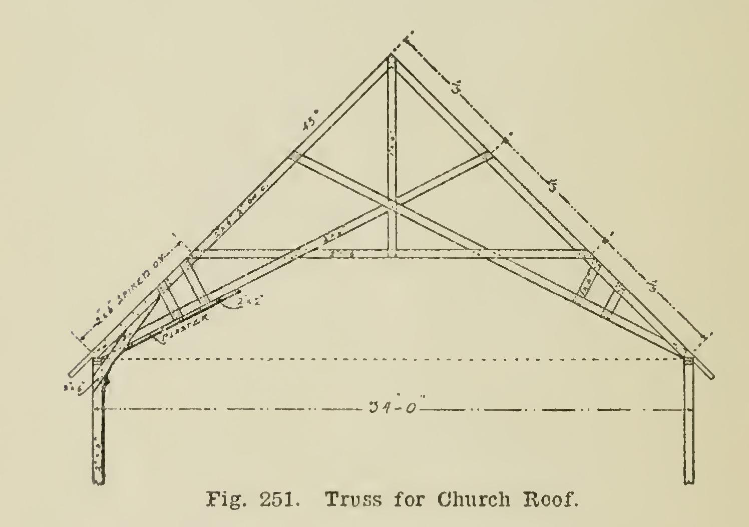
Trussing a Church Roof. Fig. 251 shows the proper way to truss a church shingle roof on a span of 34 feet, using 2 by 6 for the rafters, with roof having a pitch of 45 degrees, the ceil ing being six feet above the plate.
The timbers required are 26 feet in length for the common and tie rafters, and 24 feet for the collar beam. At the seat of the rafters is
a two-by-six piece circled out to form a cove, as shown. This piece should be thoroughly spiked to the studding, and to the side of the tie rafter, and to the under edge of the common rafter. However, only one-third of these pieces will catch the rafters, owing to their being spaced on 24-inch centers, thus requiring the other pieces to be framed in between the rafters. Other timbers in the truss are of one-by-six fencing plank. All parts should be thoroughly spiked together. Cross-pieces of two-by-two stuff are used to receive the lath, for which we recommend using expanded metal lath.

Two-by-six studding should be used for a building of this kind. What is called "two-by four" is really only three and five-eighths in width, which is too narrow, even if stout enough to give the proper width at the window-jambs to receive the sash and other trim.
Framing Rafters for a Dome.
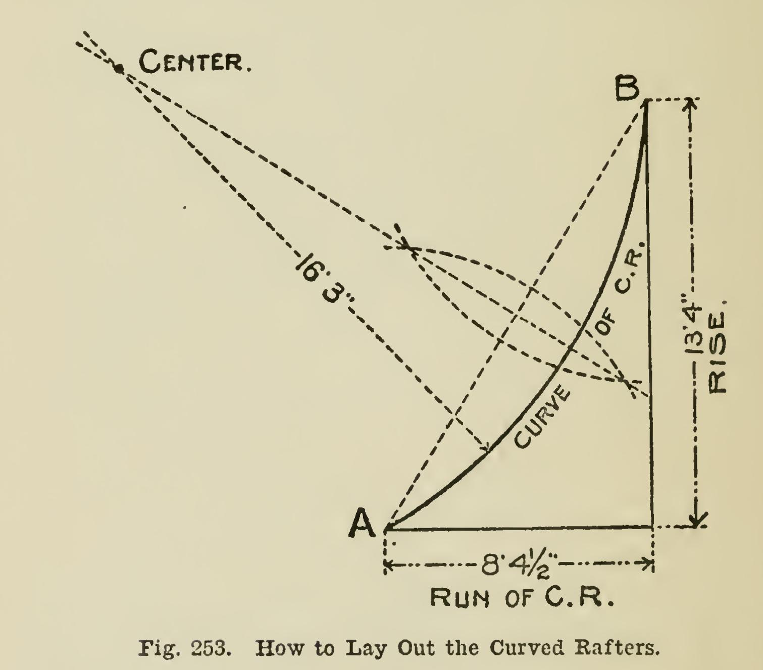
Fig. 252 shows how to frame the rafters for a dome on a public building. The plans call for an octagon dome 24 feet in diameter at the base, with an octagon deck 7 feet 3 inches in diameter, the main rafters having a rise of 13 feet 4 inches, curved to a radius of 16 feet 3 inches. To deter mine the radius of the hip, so that it will hold its true octagon angle at the corners, is a prob lem to some.
Fig. 253 shows how to proceed to lay out the curve for the common rafter, which should be made full-size. From this it will be seen that the method is the same as for finding a segment arch for an opening equal to A-B. This cannot be done for the curve of the corresponding hip, because it is not part of a true circle, as it par takes more of the oval shape and consequently has no fixed center from which to strike the curve. Therefore, to arrive at the correct curve, it should be worked out by drafting in the ordi nary way of developing corresponding curves. The seat and plumb cuts should be reckoned from the line A-B, applying the square to the same as if it were the gauge-line of the rafter.