How to Roof a Circular Bay
square, rafter, line, scale, curve, shown and common
To Develop Curved Rafters.
A question that frequently comes up for solution, in get ting out rafters that have a sweep or curve, is how to make the hips without scribing them from the common rafter, and make them so that all parts will line up properly. The method is shown in Fig. 64, which is self-explanatory. The curve for the common rafter can be any thing desired, and should be laid off full size.
Fig. 64. Developing Curved Hip Rafter.
In the illustration, A B represents the run of the curve for the common rafter, and C B the same for the hip. B D represents the rise; and it necessarily follows that A D represents the curve given the common rafter. For a square-cornered building and where the pitch is the same on both sides, the run of the hip will necessarily rest at 45 degrees from that of the common rafter as shown.
Next, lay off any number of lines parallel to the run of the common rafter; also a like number with corresponding spacing parallel to the run of the hip, but to be of indefinite lengths, as shown. Now, draw lines from the curve of the common rafter (A D), and at right angles to the run (A B), intersecting the run of the hip (C B), thence at right angles indefinitely. The intersection of these lines with the cor responding parallel lines of the hip, will give the points from which to run an offhand curve to correspond with that of the common rafter. Rafter ends of various fancy slopes, such as are used for bungalows, are developed in a similar way.
For particular work, the curve of the hip should be backed. Measure back one-half of the thickness of the hip on the parallel lines, which will give the gauge line along the side of the rafter from which to remove the wood to the center as indicated by the first curve devel oped.
How to Use the Octagon Scale. On the tongue of almost all steel squares, there is a row of dots enclosed between two lines, and figured to a scale of tenths. This scale is called the octagon scale, and is designed for changing a square timber to an octagon, or for finding the width of the side of an octagon of a given diameter. In Fig. 65 is shown a part of this scale. But very few understand it, or are even interested enough in it to look it up. It is quite evident that the inventor did not under stand the use of the plain steel square with its standard scale of measurement, which is suffi Fig. 65. Octagon Scale and Another Method.

cient for solving all problems of this kind, for lie wandered from the path of simplicity into a byway to exemplify a single problem in the polygons, then leaving the would-be learner ignorant of any apparent reason why his scale gives correct results. The solution is as follows: Suppose it is desired to change a seven-inch square stick to an octagon. Lay off a center line on all four faces of the timber; and from either side of this line set off a space equal to seven of the spaces shown on the steel square, which will be the point for the gauge line, from which to remove the wood at the corners to form the oc tagon.
These same proportions may be found direct ly from the steel square; in fact, Fig. 65 shows a rule that applies not only to the octagon, but to any of the other polygons as well.
Draw an indefinite line from 12 and passing at 5 as shown. Now, if the timber is seven inches square, measure back that amount from 12 on the tongue, and square up to the diagonal line, as at aa, which will be found to be 2 11-12 inches and represents the side of the octagon. If the timber is 16 inches, then bb represents the width of the sides and is found to be 6 2-3 inches. This rule, as we said before, applies to any of the polygons. The starting points on the square are the figures that give their respective miters, and the diagonal line across the square is governed accordingly.
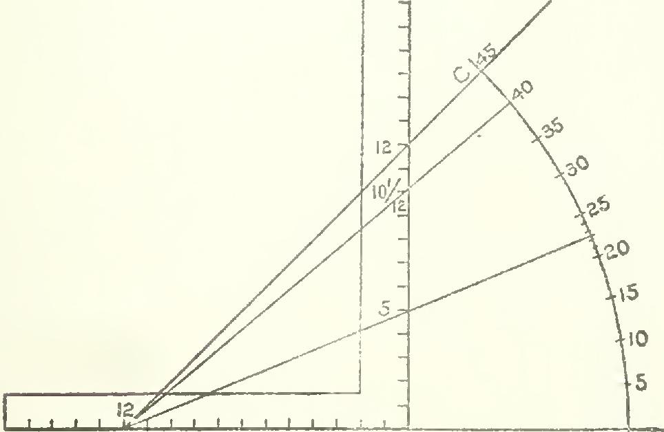
How to Frame by Degrees With the Steel Square. The steel squares that are in general use do not contain a degree scale for framing purposes, though unquestionably it would be a good thing instead of some of the obsolete rules that now encumber its faces. However, in the absence of a protractor, the angle may be found as shown by the accompanying illustration, Fig. 66, as follows: Lay off a line, as at AB, and apply the square as shown, and draw line AC from 12 on the tongue and passing at 12 on the blade. This line will be at an angle of 45 degrees to AB. Now, with the compass, strike an arc of any ra A Fig. 66. To Lay Out an Angle with the Steel Square.