Classes of Structural Members
beam, load, loads, times, beams, strength, concentrated, width and supports
32. Loading of Beams. Beams may be loaded by a uniform load—that is, a load of so many pounds for each foot of length; or they may be loaded by concentrated loads—that is, by loads that come in certain places, somewhat as if a person were to set loads of given weights at certain points. A beam may have one or more concentrated loads upon it. It may also have a uniform load and concentrated loads on it at the same time. Figs. 29, 30, and 31 show these dif ferent methods of loading, and how they are in dicated in drawings. In case a beam has both concentrated and uniform loads on it at the same time, the stresses due to the two classes of loads are worked out separately; and then these stresses are added together for the design.
A wheel on a beam is considered as a concen trated load, since it touches the beam at one point only. Wheel loads are usually designated as wheel loads, to distinguish them from concen trated loads, since they can be moved about to any and every point on the beam, while concen trated loads cannot. Concentrated loads, in fact, are often spoken of as fixed loads for the very reason that they cannot be moved.
33. Strength of Beams. The problem of comparison of beams must be made with those having an equal number of supports and either carrying the same load or being of the same size. In the first case, the sizes are compared; while in the second case, the carrying capacities are compared.
For example, let four wooden beams be taken which are as in Fig. 32, and let them all be 8 inches wide and 16 deep. It is required to show how much each can safely carry. If they are of oak, the wood can be stressed up to 2,000 pounds per square inch, and still be safe, provided the load is a fixed one. The method of designing a beam is given in Article 38. Let the load be uni form in each case. Table IX gives the results.
It v. ill he seen that the cantilever beam is the weakest, and that the overhanging beam is the strongest, while the restrained beam is in be tween. Other considerations, however, make the simple beam the most economical. The oh jection to the cantilever is that it is far too weak for a given section. The overhanging beam would tend to fly up at one end when the load first came on it; and after the load was in the middle, the ends would tend to fly up. This would require additional expenditure in the first case, to hold the beam down to the supports; and in the second case, the moving up and down of the ends would keep this class of beam from being used in any work except when the load was on it all the time. The objection to the re strained beam is that if either of the supports settled while the load was on it, the beam would be stressed above what was allowed, and per haps made to fail.
In case it is impossible to secure a second support, the cantilever must be used; otherwise it is inadvisable.
From the foregoing, the following rule may be deduced: Use a simple beam in all cases where possible. If the beam is of the restrained variety, treat it as a simple beam, and then the settlement of the supports will not stress it enough to make it dangerous.
The stiffness of beams is sometimes an im portant factor.
The strength of a beam of given span de pends upon its depth to a greater degree than upon its width. It is a well-known fact that a board will carry more when stood up on edge than when it is lying flat. The depth being in creased will rapidly increase the strength of the beam, the width remaining the same. The fol lowing is true: Increasing depth 2 times increases strength 4 times.

CS 44
3 ,, 9 times.
,, 4 Li " 16 times.
it 44
5 de td " 25 times.
It is not so with the increase in width, the depth remaining the same. The strength is dou bled if you double the width; it is made three times as strong if you make the width three times as great; and so on.
If the size of beam remains the same, then the longer the span, the less load it will hold.
Making the span times as long makes the strength 1/4 of at first ig tt ,g 4 g, tt if t4 it tt 1110 ti 14 it And so on.
Any beam will carry just one-half as much load when the load is a concentrated load at its center, as it will if the load is distributed over the entire beam—that is, a uniform load. Fig. 33 illustrates this.
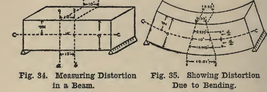
34. Stresses in Beams. When a beam is subjected to a load, it bends; and in order that it may bend, the top part must shorten and the bottom part lengthen. Of course this shorten ing and lengthening is very small, and cannot be detected by the naked eye; but this distortion is what stresses the beam. If sections a-a and b-b were marked on the beam with a very sharp in strument (say a knife edge), and these sections were the same distance apart throughout their length (say 10 inches, see Fig. 34), and then, if the beam were bent by loading it until computa tions showed that the most stressed parts of the beam were stressed to 2,000 pounds per square inch, and the distances between the two sections were then measured at the top and bottom, it would be found that the top would be almost one-hundredth of an inch shorter, and the bot tom one-hundredth of an inch longer. Fig. 35 shows this, the bending being greatly exag gerated. If a line c-c had been drawn along the beam at its middle, and the distance between the two sections measured before and after bending, it would have been found out that the distance was the same on both sides.