Concrete Pile Foundations
core, piles, inches, jet, hammer, fig, steel, hole and plates
Fig. 87 shows a section of the Raymond pile core. A represents the shell, driven in the ground; B, the exterior plates in. thick) of the pile core; C, the stem of the pile core, made of extra heavy pipe of diminishing diameter as the lower end of the pile core is approached; D, the wedge-shaped castings fitted to the exterior plates; E, the corresponding wedges fitted to the interior stem (this wedge is made of a steel casting, which also acts as a collar for coupling together the various sizes of pipes forming the stem) ; F, hinges linking the exterior plates and interior stem of the core (note their position when core is expanded) ; G, the head of the core, made of cast steel hollowed out at the top to receive an oak cap block, which receives the blow of the hammer; II, keys to keep the exterior plates in place when expanded; K, cross section, showing opening between plates to allow for col lapsing; L, steel leads of driver.
Fig. 87 is a sectional view of the core, showing col lapsing and expanding device. (Steam hammer in the leads resting upon the core.) In this illustration the shell is driven and the core expanded.
The reinforcing of concrete piles with steel rods is sometimes found to be desirable. In the case of the Raymond pile, the insertion of the reinforcing material is done prior to the placing of the concrete. This opera tion is extremely simple, is done in plain sight, and requires no unusual skill.
Should a concrete bond be desired between the butte or heads of the piles and the superstructure, that portion of the pile projecting above the surface of the ground is stripped of the surrounding shell. Thus, a larger bonding surface is offered than could otherwise be obtained.
The (how pile, as shown in Fig. 88, has an en larged footing so as to give it larger bearing, and is formed by washing down a tube with a water jet to a firm strata, and then enlarging the bottom of the excavation by an expanding arrangement to form the base of the pile. The apparatus is withdrawn, and the space filled with concrete.

In many cases where too many boulders are not liable to be encountered, piles of rectangu lar or round shape are built horizontally upon the ground, reinforced with steel rods, and, after setting for at least a month, are driven with a pile-driver. A special form of cap is required to break the force of the ram on the head of the pile. The corrugated pile is a special type of driven pile.
Fig. 89 shows a typical cross-section of the Gilbreth corrugated pile. This particular ar rangement of the corrugations was adopted for reasons of economy in the construction of the forms. At first glance it looks like a circle, but in reality it is made as an octagon or a hexagon, with grooves that do not diminish at the small end of the pile, although the pile tapers from 16 inches across at the larger end to 11 inches at the smaller, lower end. The reinforcement
shown is electrically welded fabric, and the size is approximately wires, 3 inches on cen ters longitudinally, with approximately wires, 12 inches on centers around the pile. The hole in the center is made inches in diameter at the top of the pile, and 2 inches at the bottom of the pile. This hole is made tapering for two reasons: (a) So as to have a large quantity of concrete, in the lower end of the pile.
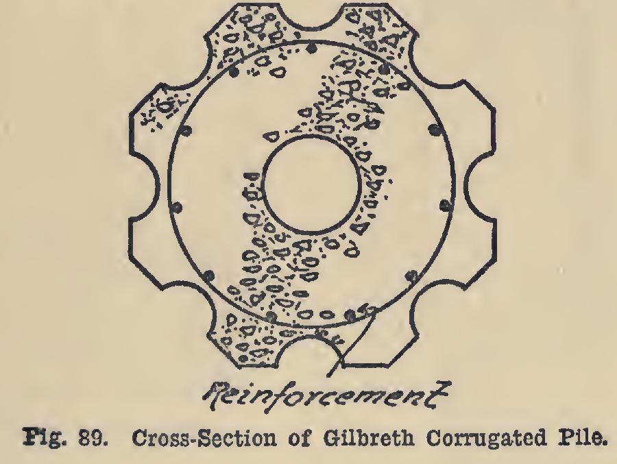
(b) So that the tapering plug that is used to cast the hole in the pile can be easily withdrawn.
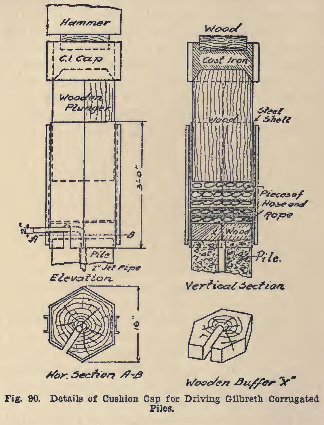
This pile is driven by means of a jet of water and a heavy weight, the weight to be used as a hammer when necessary. The pile-drivers used are of the ordinary type used for wooden piles. The piles are hoisted into place ready for driv ing; the cushion head, as shown in Fig. 90, is lowered over it; the water jet placed down into the center of the pile; and the pressure turned on. The jet extends through the entire length of the pile and protrudes three inches below the bottom of the pile. The tremendous pressure of the water is sufficient to dig a hole and carry the loosened sand, gravel and earth up the cor rugations, which act as an exhaust to the jet. The weight of the hammer pushes the pile down into the hole. When the pile is nearly in place, the hammer and cushion cap are hoisted up, and the jet is removed, the cushion cap is again low ered over the head of the pile, and the hammer forces the pile to refusal. A large amount of alternate layers of old rope and rubber-lined canvas hose forms a cushion sufficient to protect the pile from injury in driving.
In the moulding of these corrugated piles, one side of the hexagonal or octagonal mould is left off, so that the concrete can be properly tamped and thoroughly inspected at all times by the foreman and the inspector. One of the features of this pile is that there is no guesswork regarding its construction, or regarding the location of its reinforcement.
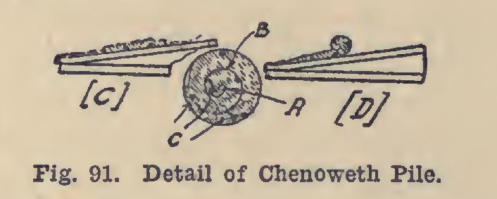
In the Chenoweth System of concrete piles and cross-ties for steam and electric railway work, no forms are used. A reinforced concrete pile is produced simply by rolling a sheet of con crete and metal netting into a solid cylinder, as shown in Fig. 91. Piles thus formed can be made in long lengths and a wide range of di-' ameters. The principle involved is that the compressive value of concrete is many times greater than its tensile strength. In this con struction, the reinforcing members act indepen dently, the concrete carrying the load action under a compressive stress, while the steel rein forcement resists the tensile stress.