Concrete Pile Foundations
platform, piles, netting, wire and fig
Referring to Fig. 91, A is a steel pipe or rod ; B is a coiled sheet of wire netting; and C are longitudinal steel rods, placed near the periphery, equal distances apart, parallel to the longitudinal axis of the pile. The pipe or rod A forms the shaft or mandrel on which the pile is rolled or wound, and the netting B and rods C constitute the reinforcement.
The apparatus for rolling the pile consists of a trav eling platform, between which and a roller the pile is formed. The winding pipe or mandrel is set in line of the shaft of a large spur wkeel. In operation the steel wire netting with the longitudinal rods attached is spread on the platform and covered with a layer of concrete, as indicated by the sketch C, Fig. 91. One edge of the netting is attached to the edge of the platform, and the other edge to the winding pipe or mandrel. Thus ar ranged, the winding mandrel is rotated, and the netting and its covering of concrete are wound or coiled up as indicated in sketch D. At the same time and as fast as the netting and concrete are coiled up, the platform A moves under the roll B and the roll itself rotates.

The forming cylinder of concrete is by this means kept under constant and heavy pressure between the platform and roller. To bind the roll of concrete, wires are wound around it at close intervals and tied. The wires are contained on spools arranged beneath the moving plat form. These spools are spaced every 6 inches along the pile and fastened to the wire mesh, so that when the pile reaches the lower edge of the platform it can be revolved about the axis, causing the wire to be wound on the pile.
In this manner the wire is passed around the pile a number of times and secured. At the driving end of the pile, the spools are placed 4 inches apart for the first 6 feet of the pile, and then 6 inches apart for the remainder of its length. The pile is removed from the machine by rolling onto a car, when it is transported to a platform, where the point is formed, flushed up, or smoothed, if desired, and allowed to remain until it hardens.
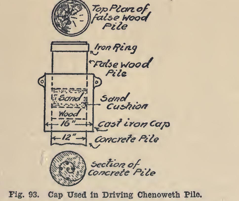
Fig. 92 shows the reinforcing members of a Chenoweth concrete pile 14 inches in diameter and all lengths up to 75 feet.
Fig. 93 shows the detail of cap used in driving these piles. It was found that this cap would protect even the sharp edges of the top of the pile, provided the pile was made eight days before driving.