Concrete Arch Bridges
arches, stones, ft, piers, abutments, square and spandrel
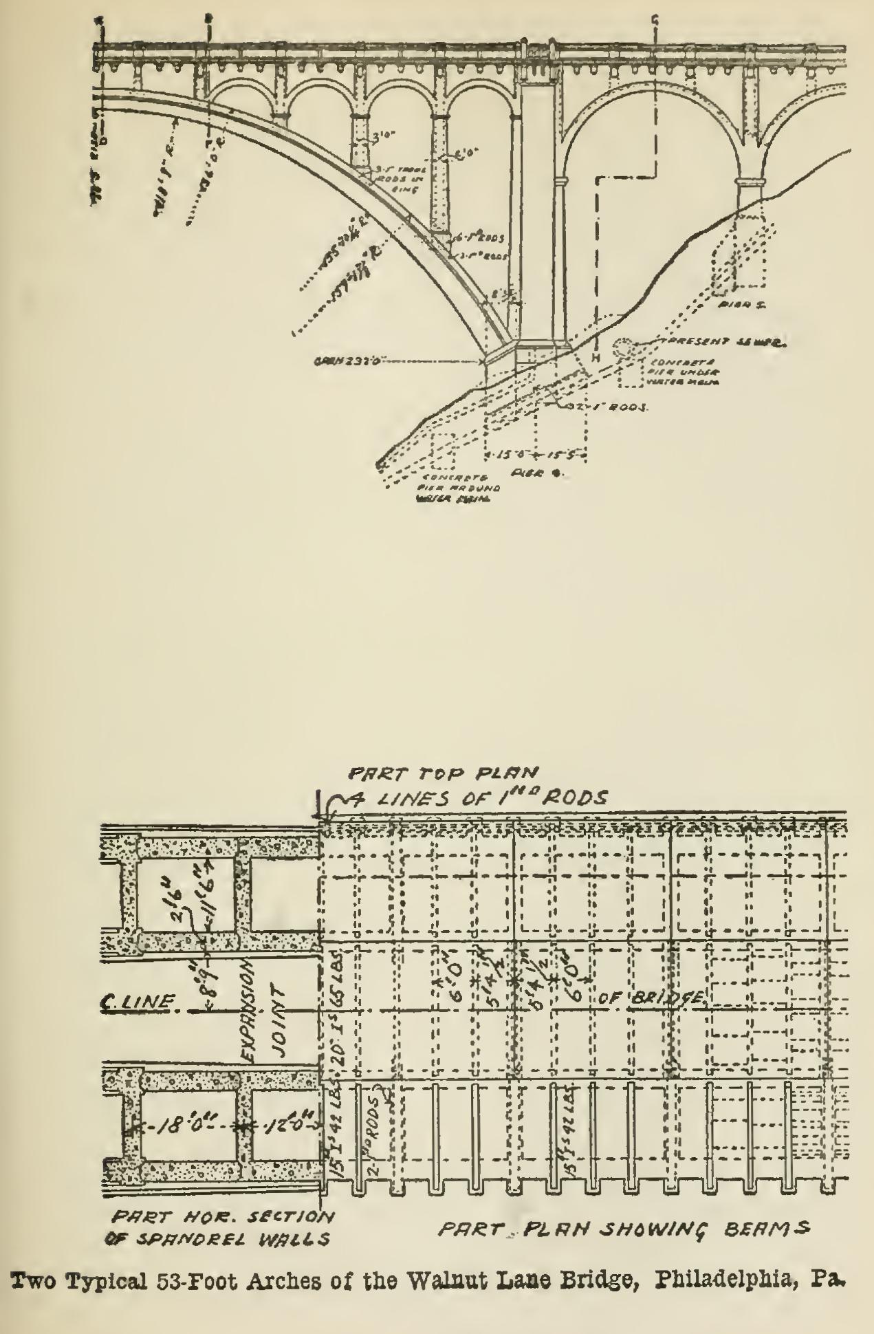
The abutments are reinforced near the bottom by one plane of 1-in. square rods parallel to the springing face of the arch and running transverse to the line of the bridge.
From each arch-ring rise T-shaped cross walls of con crete, which act as supporting piers for the spandrel arches. There are in the line of the bridge two of these pillars and accompanying arches to each arch-ring, mak ing four lines of spandrel arches. The pillars nearest the abutments are bonded with the arch-ring by 1-in. square rods. The arch-ring is reinforced under each pillar by three 1-in. square rods running transverse to the line of the arch.
The floor system is carried on I-beams, 15-in. 42-lb. beams on the outside, and 20-in. 65-lb. beams in the mid dle, which span across the spandrel walls. These I-beams are tied together by tie-rods, and the floor system is carried between them by jack arches. Over the span drel walls and main piers, the 15-in. I-beams are omitted, and 1-in. square rods are substituted as reinforcement.
The roadway is made up of a cinder-fill on top of the embedded I-beams mentioned above, topped off with a 6-in. layer of concrete and a final 31/2-in. layer of asphalt. The sidewalk is of concrete reinforced by 1-in. square rods.

The railing is of concrete, with the pedestals and pilas ters cast in place, and the balusters moulded separately and set afterward. All copings, moulds, and cornices that project from the main face of the wall are reinforced with small rods bonding back into the wall.
Expansion is provided for by making each floor sys tem between spandrel pillars fixed to one end pillar and movable on the top of the other.
The small approach arches are 53 ft. in span, and 1 ft. 6 in. arch thickness, with an exposed arch face 2 ft. 3 in. deep. All the details of columns and floor beams are the same as in the large arch, except that there are no spandrel arches, the outside face being carried to the floor level by a solid wall.
The material used in the construction might be called a rubble concrete. In all foundations, stones of derrick size were allowed to be embedded, and smaller stones embedded with them, but not closer than 2 in. to any face. The concrete in the abutments to the main arch and used in the rest of the work, except the arch-rings, consists of a 1:3:6 mixture, the crushed stone varying from to in. in size. This is supplemented by
the use of stone varying in size from 12 in. largest diam eter, to sonic stones of derrick size. These stones, rough and sharp from the quarry, were deposited in each layer of the concrete when it was in a plastic state, and rammed down to about their mid-depth, thus leaving a bonding line of stones sticking up from each finished layer. The main requirement of the engineer was that these bonding stones should be deposited in a soft concrete so as to have opportunity to get the full benefit of the setting process. In the abutments to the main arch, the embedded stones are of flat shape, an effort being made to place them in a plane normal to the direction of the resultant thrust of the arch.
When this large-stone process was extended to the areh-rings, a 1:2:5 mixture was used, the embedded stone being not less than one-man size and of such shape that their thickness was approximately one-quarter of the average dimension. They are laid radially in a way resembling the voussoirs of a masonry arch. At the points covered by the spandrel piers and walls, a number of these stones project above the areh-ring to act as dowels.
Railroad Arch Bridges. Plate 4 is an illus tration of a 4-span skew railway arch bridge over the Sangamon river near Decatur, Ill. The arches have a clear span of 58 ft. in., meas ured on the square, while the piers are 100 ft. center to center, measured along the center line of the bridge. The rise of the arches is 30 ft. At each end are long, hollow abutments. Fig. 39 shows a plan and elevation of the bridge.
The concrete is made of gravel, and its com position is as follows: For arches, slabs car rying tracks, and footings for piers, 1 :5. For piers, spandrels, abutments, and lower slabs, 1:3:6. The assumed live load on the structure was 9,000 lbs. per linear foot for each track. The allowed working stresses were 600 lbs. per sq. in. for compression in the concrete, and 12,000 lbs. per sq. in. for tension in the steel.
Plate 5 is an illustration of a double-track railway bridge of one 100-ft. and two 80-ft. arch spans.
