Concrete Retaining Walls
mould, wall, ft, moulds, shown, track, tower, sectional and sheeting
The waling pieces are fastened at the corners of the moulds by IT-straps of iron bolted to the longitudinal pieces, and projecting beyond their ends to engage the chamfered ends of the transverse strips. Intermediately, the longitudinal waling pieces are tied together through the mould by pairs of horizontal rods in. apart, with hemispherical upset heads at each end, engaging cast-iron sockets shown in the detail, which are placed just inside the sheeting and are secured by short bolts with nuts engaging the castings. The opposite ends of the bolts have nuts taking bearing on the waling pieces. After the concrete has set, both nuts arc unscrewed and the bolts removed, leav ing the castings and the rods permanently embedded in the concrete. The mould panels weigh from 2 to 3 tons each, and are handled by the 45-ft. boom of a locomotive crane.
The first mould was assembled with both ends closed by sheeting; and after it was stripped from the concrete, two moulds were used, and sections were built on both ends alternately, allowing one section to set while another was being built. These successive sections are made with moulds having front and rear sheeting and sheeting at the outer end only, the previously finished concrete closing the rear end of the mould where the front and side panels of sheet ing overlap the faces of the concrete and are tightly clamped to it by the horizontal trans verse rods. It takes a force of 20 men about 3 hours to strip a mould; and it takes 20 men about 7 hours to reassemble it and oil the inside ready to receive the next section of concrete. In large work of this sort, it would be possible to use 3 or more sets of moulds, and prosecute the wall building simultaneously at as many points.
Concrete is mixed and delivered to the moulds without hand work, by a movable plant, which is operated entirely by electricity and which is installed in a 13 by 16-ft. wooden tower 40 ft. high, which has eight double-flange wheels traveling on a track of 13 ft. 2 in. gauge about 5 ft. clear of the face of the wall. A standard gauge track on the center line of the tower track receives material cars which run through the tower with a clearance of about 12 ft. horizontal and 14 ft. vertical, and which are unloaded by hand on a platform parallel to the track, where they are wheeled to a pair of 1-yd. steel auto matic tilting buckets operated by a hoisting en gine in the tower. The buckets run in vertical guides extending 16 ft. above the top of the tower, and deliver to two 10-yd. hopper-bottom storage bins about 7 ft. above the mixer floor, where 400 bags of cement are stored which are hoisted by whip lines operated by the capstan head of the hoisting engine.
The storage bin chutes are fitted at the bot tom with horizontally pivoted troughs which close them when raised, and, when lowered, al low the sand and stone to be discharged to the measuring hopper where the cement is emptied, and all is delivered to the mixing machine while the revolution of the latter is uninterrupted. The mixer and hoisting engine are operated by independent motors, and the mixer delivers through an inclined chute to an end-dump tilting 1-yd. steel car which runs across the top of the mould on a 24-in. longitudinal track and dis tributes the 1:3:6 Portland cement concrete as required for the laborers, who place in it one man stones and carefully spade the mortar around the sides of the mould. The concrete is mixed wet and requires no ramming. Each mould holds about 250 cu. yds.; and the best rec ord of filling it is 6% hours for 60 men, includ ing those in the tower. The moulds are stripped the next morning after being filled; and con creting for each mould is continuous until it is completed. The total number of men employed on the concreting and handling the moulds is about 75, and the largest record is 2,700 yds. of concrete in one month.

Fig. 88 is a cross-section of a concrete retain ing wall partially reinforced, as built by the Chicago, Burlington & Quincy Railroad Com pany for track elevation purposes in Chicago.
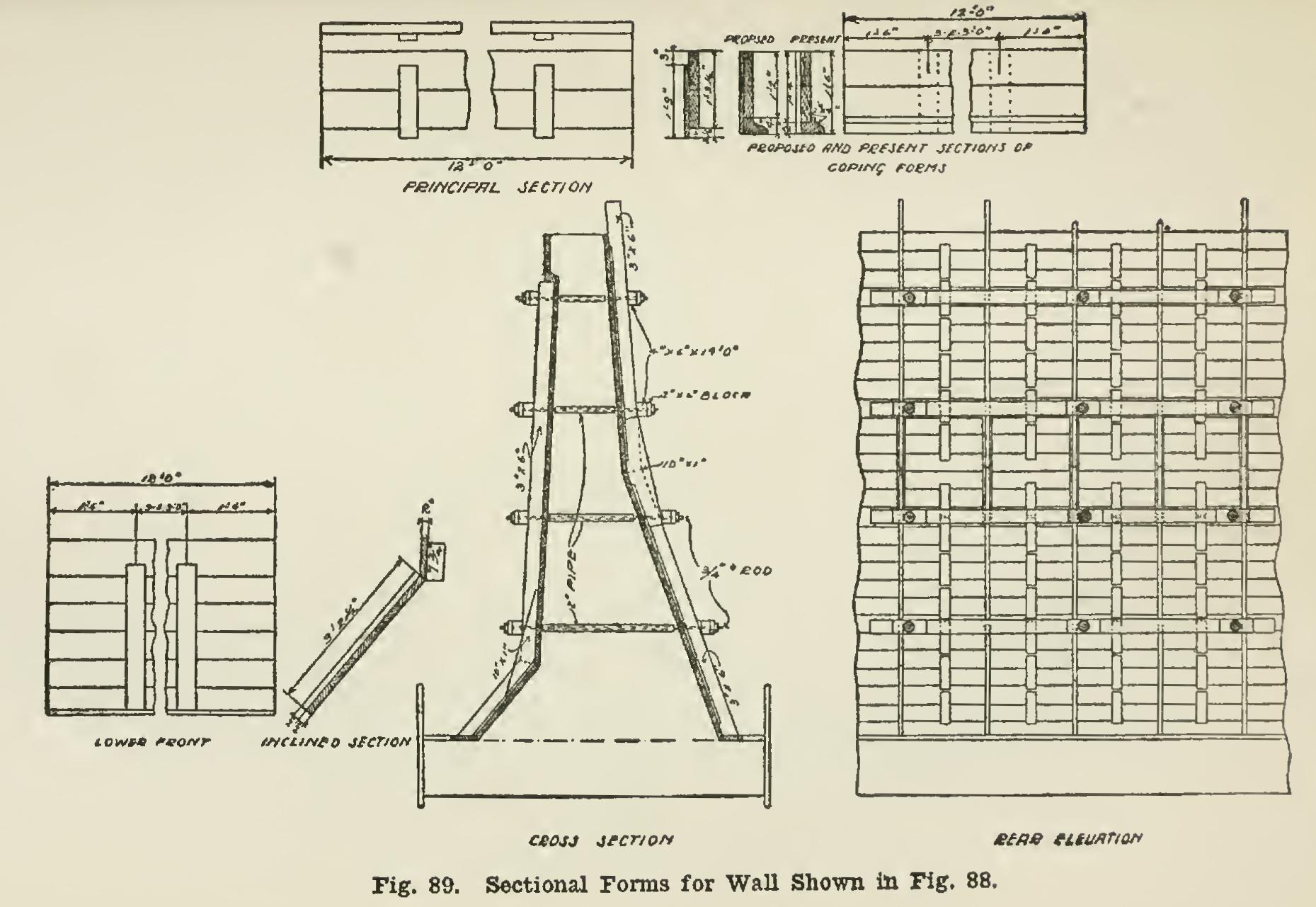
In Fig. 89 are shown the forms used on these retaining walls. They are a combination of con tinuous and sectional forms, the sectional part consisting of studs, coping, and bottom forms for the face, and sectional forms for the back of the wall. Ordinarily sheeting is used between the coping and bottom forms, the back forming being entirely sectional. All sections are made in templates, and delivered on the work in units, as shown in the figure. No attempt was made to use sectional forms on the face of the wall, ex cept as mentioned, because the sections become battered and warped with use, do not fit closely together, and leave the wall rough when they are removed.
In Fig. 90 is shown the method of bracing and tying down the forms. The cross-section of the wall is such that the wet gravel concrete used had a tendency to lift the forms off the foot ing. This did occur in one case, causing consid erable trouble. The plan shown in the illustra tion was then adopted, the bars being placed in the footing, and the forms tied to them with wires. In building such walls, it is difficult to keep them in perfect alignment. Small varia tions in the face of the wall are not noticeable, but any deflection of the coping shows at a glance. The method of bracing the coping form shown in Fig. 90 furnished an easy and effective way of lining up that form.