Concrete Retaining Walls
wall, earth, weight, back-fill, built, fig, material and thrust
CONCRETE RETAINING WALLS A retaining wall is a wall built for the pur pose of supporting or holding back a bank of earth, rock, or other loose material. Such a wall is required wherever it is necessary to have an abrupt change in the level of the ground sur face, and where it is not desirable, because of lack of space or for some other reason, to let the earth run out to its natural slope.
Because retaining walls are partially buried in the ground, and because they must endure indefinitely, they are constructed of masonry. Stone masonry walls depend on their weight to hold back the earth behind them and are sel dom built nowadays, concrete being used in stead. The use of reinforced concrete has made it possible to construct a number of economical types of wall which could not be built of plain concrete or stone.
The material behind a retaining wall is termed the filling or back-fill. This material has a tendency to slope out to an inclination which is less steep when fine, loose, or wet than when coarse and compact. The wall must be designed in such a way that it will resist this tendency of the back-fill to spread out; or, in other words, it must be designed so that it will not be pushed forward or overturned by the thrust or pressure of the back-fill. The thrust of the back-fill depends on the steepness of its 246 natural slope; and this, in turn, depends on the nature and condition of the material. As an ap proximation which has been assumed to repre sent average conditions, the horizontal thrust of earth filling at any depth is considered to be equal to one-third of the weight of the earth above this depth.

The tendency of retaining walls to slide for ward is prevented by the depth of the founda tions or by the use of piles. Walls are designed to resist overturning in two ways: 1. They are built of sufficient mass and weight.
2. They are constructed to utilize the weight of the earth resting on the back projec tion, or heel, of the wall.
The first-mentioned walls are known as gravity walls. Fig. 83 is a cross-section of a gravity wall. A safe rule for the design of such a wall is to make the width of the base b equal to of the height h.
The walls which utilize the weight of earth on the heel are of three distinct types, as shown in Figs. 84, 85, and 86.
Fig. 84 shows a wall of L section, with the position of the main reinforcement indicated.
Fig. 85 shows a wall of T section, the toe pro jections being about 1/2 of the heel projection.
Fig. 86 is a section of a counterfort retaining wall. In this type, which is the most economical for very high walls, the face and footing slabs span between the counterforts, which are ten sion members spaced at distances about equal to the width of the base of the wall. The width of the base of reinforced walls should be equal to about one-half of their height, instead of as in the case of solid gravity walls.
The preceding discussion of the design of retaining walls will indicate some of the pre cautions to be taken in construction. It is essen tial to secure a good foundation, deep enough to be safe from the action of frost and all danger of undermining, and firm enough to resist the forward thrust of the filling and the weight of the wall and superimposed earth. It is impera tive that the design shall be carried out, and that bars and joints shall he put where they are called for, and nowhere else. The back-fill should be properly placed and well drained.

The form work used and the method of pro cedure adopted in building walls of various types, as illustrated and explained in the fol lowing pages, will familiarize the concrete worker with these structures in a better and more practical way than a theoretical discussion would.
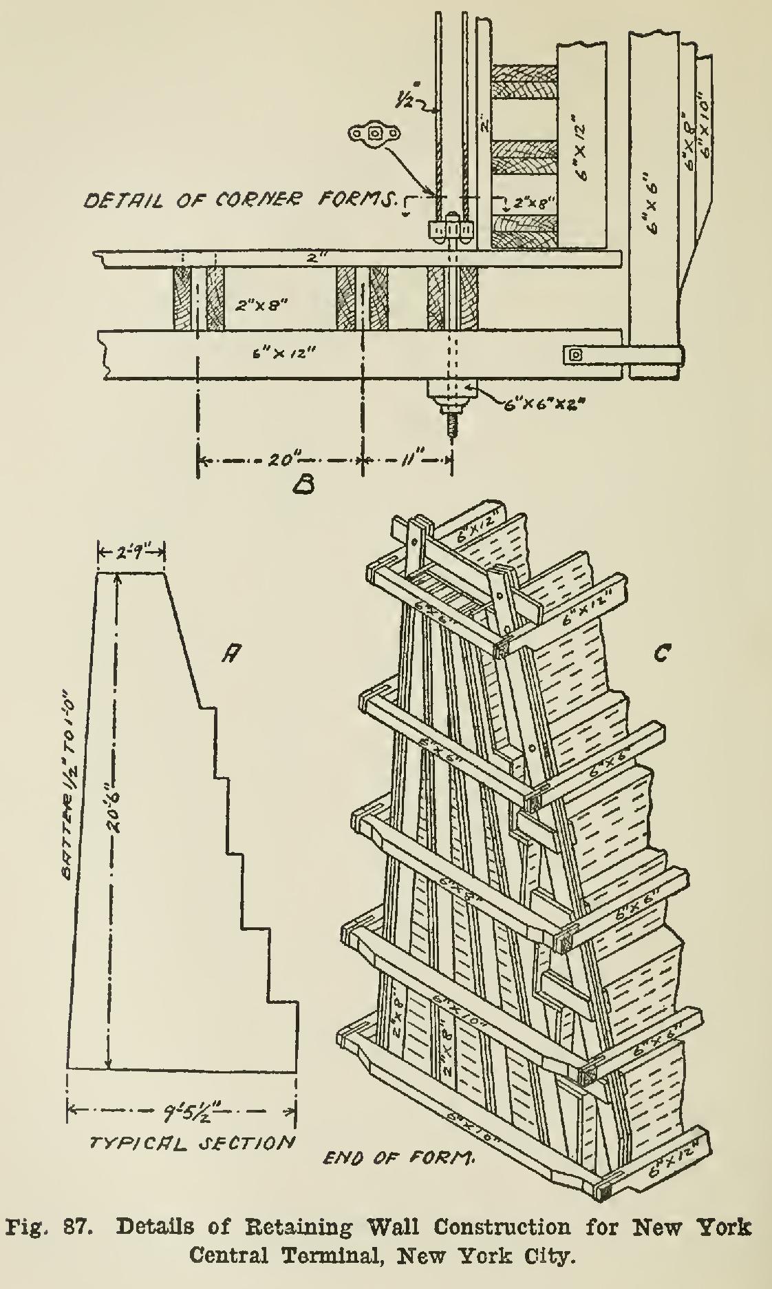
At the Grand Central Station of the New York Central Railroad, the yards have been ex tended to a total area of about 43 acres, and are depressed to an average distance of about 20 feet below the adjacent streets, being enclosed by a massive concrete retaining wall (see Fig. 87, A, B, and C). The wall varies from about 11 to 21 ft. in height, and has a batter face with rear offsets 3 ft. high, as shown in the cross-section. It is made in full-height sections about 52 ft. long, with open vertical transverse expansion joints in. thick between them. The moulds are built with horizontal 2-in. Virginia pine planks, ship-lapped 1/2 in., and laid in. apart to allow for swelling. They are lined on the face with thin steel plates, and are secured by vertical spruce joists and removable horizontal yellow pine waling pieces, bolted on as indicated in the illustrations. The front and end sheeting is made in single large surfaces; but the rear sheet ing is made in steps to correspond with the off sets, each one having a vertical and a horizontal part fitted to the framework like the tread and riser of a stair.