Fireproof Construction Floors
floor, joists, tile, placed, concrete, top, inches, space, method and feet
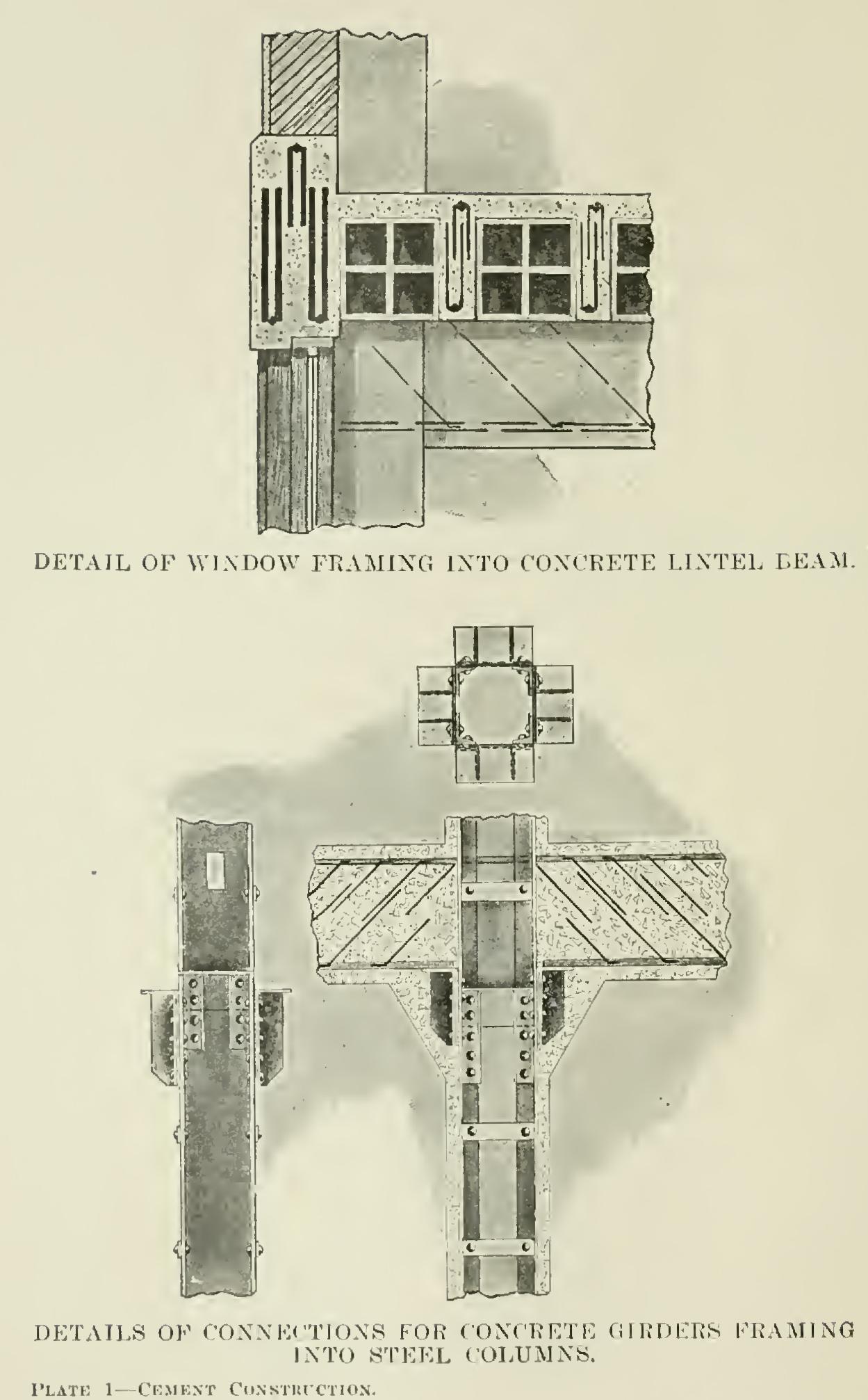
Plate 1 shows details of connection for con crete girders framing into steel columns.
Fig. 9 shows a clamp used in holding wooden forms together during the construction work.

This clamps around the corners of the forms, and, when in place, is set up tight by hitting on free end of bar.
Plate 2 shows a form of shaft-hanger insert.
These are attached to the forms during the con crete construction work, and completely em bedded in the concrete. The long slot allows considerable variation in the location of the shafting. Standard lengths of these inserts are three feet, but they are made in a single casting in lengths up to six feet.
Plate 2 also shows a socket insert for attach ing sprinkler systems, fixtures, shaft-hangers, etc., to concrete work. They are made in two sizes, cored and threaded for and bolts.
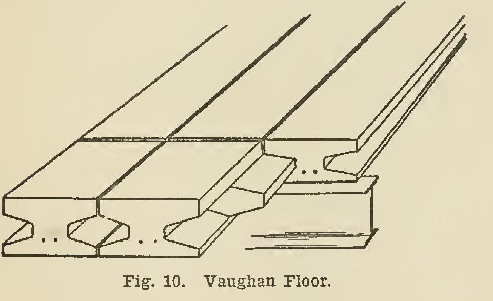
The manner of bonding and laying the indi vidual joists in the Vaughan system of floor con struction present a few points of interest which are shown in the accompanying figures. Where there is sufficient head-room, the joists can be placed on top of an intermediate I-beam support, simplifying and cheapening the erection. When the joists are placed on top of an intermediate support, as shown in Fig. 10, a simple and posi tive method of tying the two sides together is the use of a cant concrete block fitting into the hollow space between the joists. This block is wrapped once with very coarse burlap. When placed, this is wet down and submerged into a wet mixture of one part cement and one part sand, the meshes of the burlap forming pockets which retain the mixture and prevent it being scraped off when put in place.
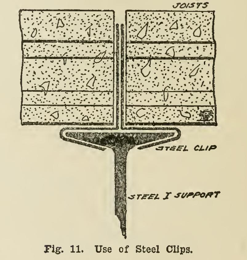
When the joists are placed on top of an I beam for an intermediate support, two steel clips can be fastened over the top flange of the I, and the ends of the joist placed against their turned up ends, as shown in Fig. 11. This provides a method of transmitting the transverse floor loads from the joists to the supporting beam, and would prevent its slipping to one side under any conditions.
The continuity bar or tie-rod shown in Fig. 12 is to take care of any negative bending moments due to the girder support at this point. This is necessary when a granolithic or any solid cement or stone finish floor is used, preventing abso lutely thereby unsightly cracks. Fig. 12 shows the position of the bar when the joists are placed with their top flange under the top flange of the I-beam.
When floor-joists of this type are used throughout a building, it is advisable to tie the walls together. At intervals of about 20 feet or at the intersection of interior columns, two joists can be separated by a space of about 8 inches or a full width of a column if desired. A single board placed underneath this space and supported by props—the ordinary method of supporting centering— will form a false floor on which to pour wet concrete. Long rods extending the full width of the building and turned into the wall, should be placed in the space between the joists, which should then be filled with con crete, flush to the top of the joist.

A short tie-rod can be used by the following method: The top flanges of the two joists should be broken away for about G feet next to the wall. In this space, lay a tie rod about 9 feet long, with one end bent into the wall for about 15 inches, and the other end curved into a hook shape. A wood block should be placed between the joists, filling the hollow space, to serve as an end stop, and the concrete poured in to fill up this opening. This method of tying will serve as well as the first method, when the interior ends of the joists are tied to the beams and columns in a suitable manner.
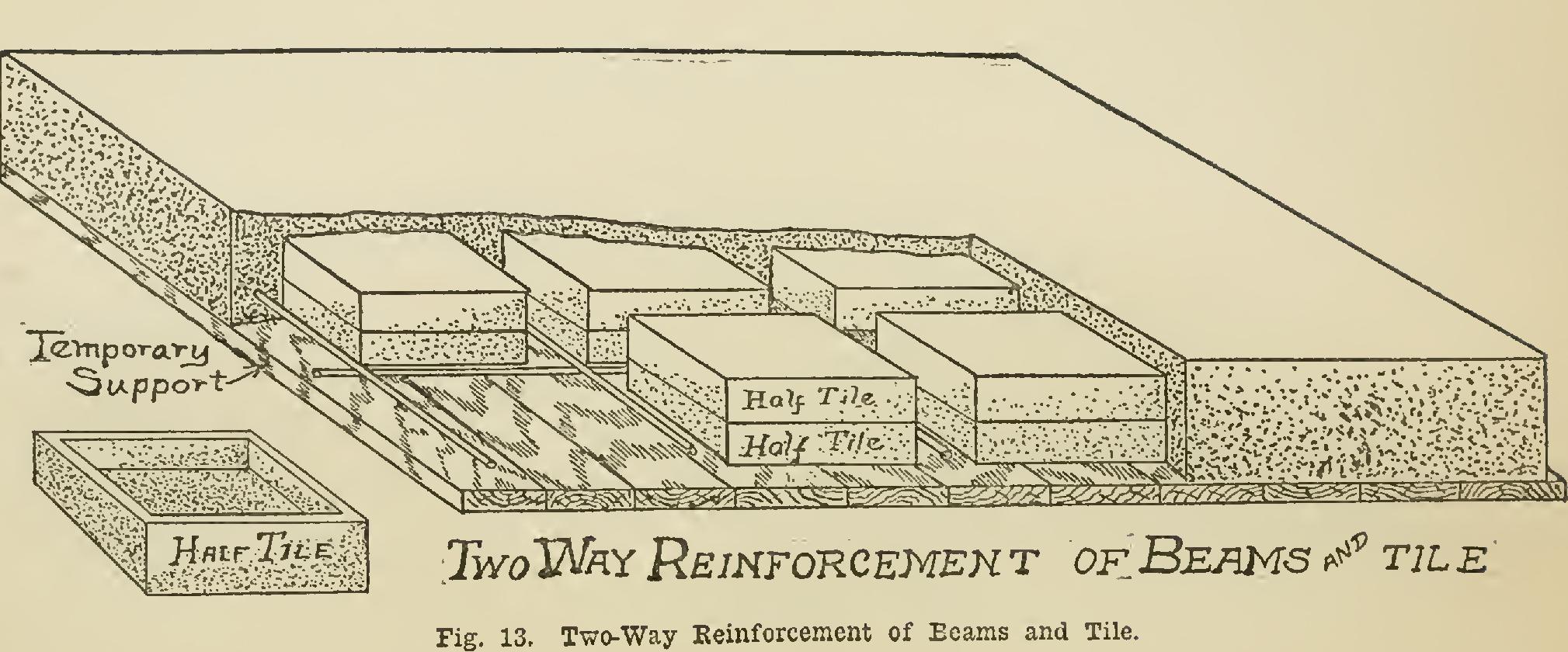
Fig. 13 shows a type of strong and light floor. In concrete fireproof floor construction we have a heavy dead load (weight of floor) on long spans, which, added to the live load, makes much additional cost on long-span work; therefore, the combination system of running beams one way, separating them with rows of hollow clay tile, has become popular; but this does not tie or bond the floor together like a two-way reinforcement.
This has led to the design of a two-way floor slab of the beam-and-tile system. The tile, being made of concrete, are 16 inches square, made of a web thick, and have the height of the space required, so that two tile make an air space or void to reduce the weight of the floor slab.
The centering is but one flat surface, the same as for beam and tile combination of the one-way type, which is much cheaper than the drop beams (panel method) and solid slab of the all-concrete floor.
These tile are spaced four to five inches apart, forming the beams as shown.
Owing to the depth of beam, this is claimed to be one of the best and least expensive systems now in use, the floor being bonded in all direc tions, as the rods (reinforcing) are tied with wire at every crossing.
Any plain or patented bar can be used, and the hollow concrete tile can be made in moulds or on machines. Thus no delay in waiting for clay tile is necessary, one part of cement to five parts of sand making a very good tile for this purpose. One part cement, two sand, and four of gravel is generally used for the beams.
The height of tile and thickness of floor are governed by the load per square foot and the length of span. A floor, for example, to carry 200 pounds per square foot, and span 20 feet be tween supports, should have tile 10 inches high (two half-tile of 5 inches each), and have two inches of concrete over them, thus making the floor-slab twelve inches thick, which will weigh about 38 per cent less than a solid twelve-inch slab, or about 92 pounds per square foot.
The plainness of the forms, saving lumber and carpenter work; the depth, saving reinforc ing; and the reduced weight and well-bonded reinforcement, make this type of construction economical in many instances. However, the ap pliances for making the half-tile have much to do with the cost.