Girder and Slab Bridges
concrete, solid, bridge, columns, spans, composed and floor
Fig. 46 shows a plan and elevation of a typi cal 20-ft. slab railroad crossing over a highway. Fig. 47 gives a cross-section of the slab.
Plate 6 (C) illustrates a cattle-pass which represents the acme of simplicity in structures of this kind. The side walls are solid concrete abutments with a low percentage of reinforcing steel used.
The top of the culvert is a solid concrete slab reinforced with bars. These bars span across from wall to wall. They are placed about 10 inches apart in the slab.
The embankment at this point is high enough to allow ample head-room, and still enough clear ance between the top of the slab and the track to permit plenty of ballast.
The first cost of this structure is no greater than if built of heavy timber, and the mainte nance cost is nil. The culvert will stand for all time, without need of repairing or replacing any portion. There is nothing to decay or rot out.
Track Elevation Bridges. One of the great engineering problems of the present day is the problem of eliminating railroad grade crossings in populous districts. In some cases the streets are carried over the tracks on viaducts, but usually the tracks are elevated and carried over the streets on bridges. These track-elevation bridges are usually made up of short spans—one span over each sidewalk, and one or two spans over the roadway. It is essential that these structures have solid waterproof floors, in order to protect the traffic in the street from drippings and falling objects from the tracks above. It is only recently that reinforced concrete has been used or even suggested for these structures; but it has so many advantages that it is rapidly com ing into common use. Among the advantages are: Cheapness in first cost, low expenditures for maintenance, permanence and durability, freedom from vibration and accompanying noise, waterproof floor, and attractive appearance.

The design of track-elevation bridges con sists in the design of the abutments, the support ing columns and the slabs.
Figs. 48 and 49 show an elevation and cross-section of a typical two-track track-ele vation bridge entirely of reinforced concrete construction.
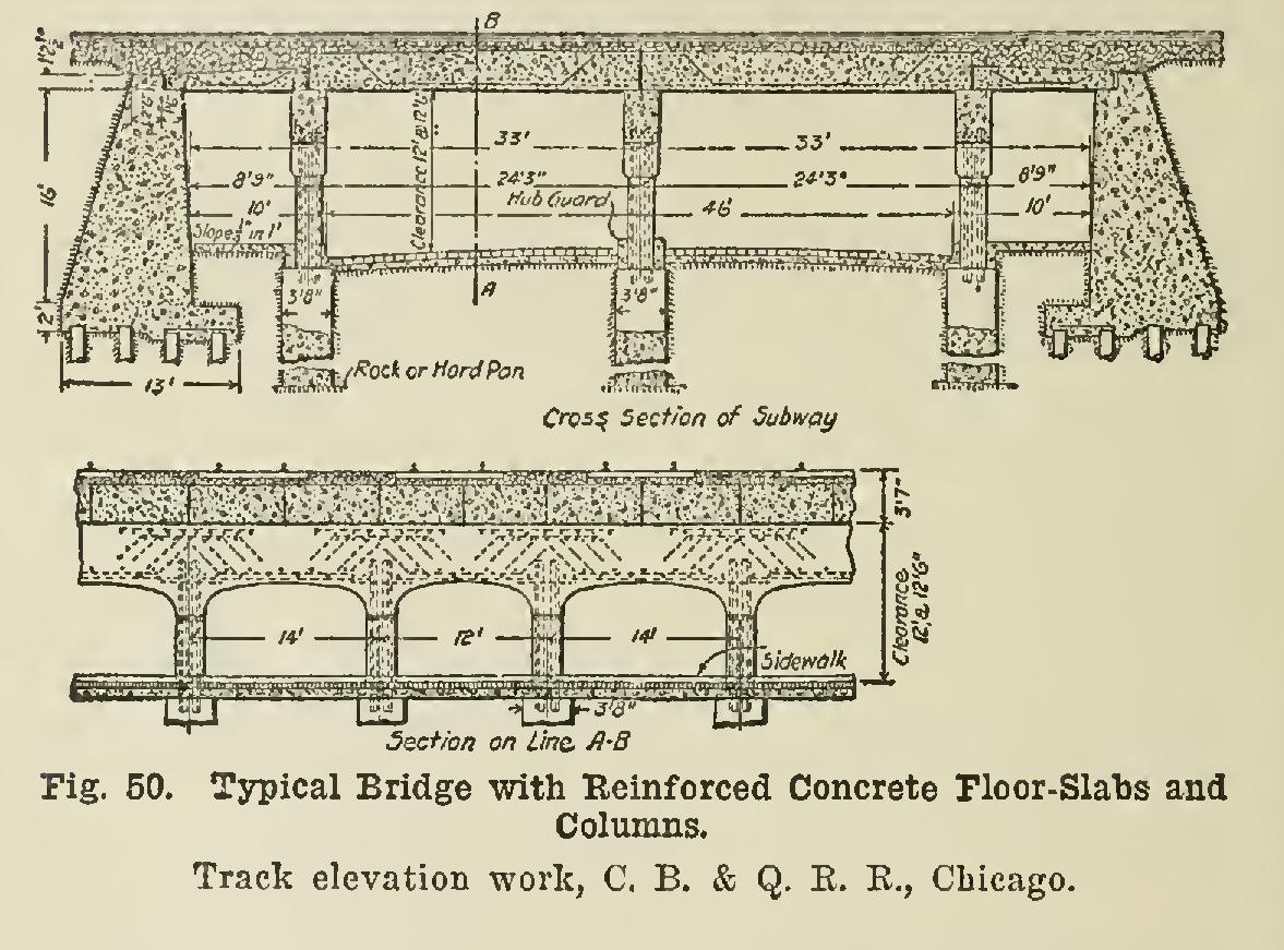
The following description of the work done by the Chicago, Burlington & Quincy Railroad in Chicago will explain the construction of con crete track-elevation bridges: The standard type of bridge used in the subways of the C., B. & Q. R. R. track-elevation work in Chicago is a ballasted-floor bridge, composed of two 24-ft. 3-in. street spans and two 8-ft. 9-in. sidewalk spans, resting upon solid concrete abutments at the street lines ; and three lines of columns and cross-girders, two at curb line and one on center line of street. The decks proper are rein forced concrete deck-girder slabs ; and the columns and cross-girders are also composed of reinforced concrete, and rest upon concrete cylinders extending down to bed rock.
The conditions to be met in the design of these bridges (see Fig. 50) were as follows : (1) Under the city ordinances the subways were to be 66 feet wide, composed of a 46-ft. roadway and two 10-ft. sidewalks, allowing the use of three sets of columns and cross-girders, one in the center line of the roadway, and the other two on the curb lines. The spans were finally determined as shown.
(2) The head-room or clearance, which is 12 ft. and 12 ft 6 in. above established grades in subways.
(3) The bridges being at the eastern end of the Western Ave. yard, it was very desirable that they be so designed that tracks and crossovers could be placed at any point upon the structure. This requirement could be satisfied only with a ballasted-floor type of bridge.
(4) As thin a floor as possible within the limits of good practice, so as to minimize the depth of fill, approach grades, and height of walls.
(5) A floor that is easily made water-tight.
(6) A floor as near sound-proof as possible.
(7) Comparative cost.
(8) Permanence.
After looking over the field for some time, it was decided that one of the three following would fill about all of the conditions : (a) A trough-girder bridge composed of a series of troughs, made of plates and angles, concreted to form a solid deck.