Girder and Slab Bridges
slabs, bars, lbs, inch, placed, concrete, square, center and days
The bending moments per foot width of girder are for center girder, 13,150,000 inch-pounds; for sidewalk girder, 7,468,000 inch-pounds; while the steel reinforce ment is 1.3 per cent and 1 per cent respectively. The girders were designed by the use of the Johnson formula, and checked back by those of Prof. Talbot, these unit stresses being as follows: Center Cross-Girder—Tension in steel, 14,850 lbs. per square inch; compression, 780 lbs. per square inch.
Side Cross-Girder—Tension in steel, 15,500 lbs. per square inch; compression, 689 lbs. per square inch.
The bars over the columns were put in as a matter of precaution, and have the same area as the main bars. The web stresses in the girders are quite high; but the shear bars have sufficient area to carry all diagonal ten sion at 12,000 lbs. per square inch stress.
Cross-Girder Forms. The 14-foot cross-girder forms were lined with metal to give a smooth surface to the concrete, and also increase the life of the form. The mixture was a 1:2:4, mixed and placed by hand, the same materials being used as for columns.
Concrete Decks. The decks were originally designed in 1905, the live load being equivalent to about E60 Cooper's loading, plus 100 per cent. This was assumed to be distributed over 10 feet of width. In checking back, it was found that the stress in the steel was 12,750 lbs., and compression in concrete, 668 lbs., per square inch ; for street slabs it w:Is 12,700 lbs., and 659 lbs. for sidewalk slabs.
Slab Forms. A cinder foundation about 2 feet deep was laid, and upon this the mud sills were placed, being carefully tamped and leveled. The main sills resting upon the mud sills were leveled up by the use of shingle wedges.

The floor consists of 2-inch tongued-and-grooved lum ber, and was spiked firmly to all the sills so as to prevent warping. On the floor a template of 1-inch boards was laid, and the sides and ends erected, these being units.
The bars were taken into the form fore the last end piece was placed, and arranged later on as needed.
In the spacing of the bars, a small V-shaped iron or saddle was used. These were spaced near the ends, center, and quarter-points, and carried a bar, transversely to which the main bars were wired after being carefully spaced. The wiring had to ,e carefully done so as to hold the bars from spreading in concreting. The main stirrups were suspended in place and boxed in before concreting. These stirrups were made of 1%-inch round iron for the street slabs, and 13/4-inch for the sidewalk slabs, and were used to engage the toggle on the derrick for erection.
The forms were given a coat of coal tar paint, con sisting of coal tar, kerosene, and cement, which gave very good results and preserved the forms from checking and warping.
The mixing plant was placed opposite the slab form to be concreted, and the material placed direct by chutes, the chute being long enough to reach well back past the middle of the form, with trap doors intermediate so that material could be placed uniformly.
The first two or three batches were smaller and con tained more sand than those later, this being done to simplify the working of the concrete around the rein forcement, which was not easy, the bars being only C. to C. for inch bars. After the lower 15 to 18 inches was in place, the work was simple, care being taken to get a well-spaded smooth surface.
The mixture used was a 1 :4 concrete of pit-run gravel, which was of fairly uniform mixture. Whenever any mange in uniformity was observed, a mechanical analysis was made of the gravel, and the required material added to give a dense concrete.
Test specimens in the form of cylinders, 6 inches diameter and 9 inches long, were taken every day and stored under identical conditions with the slabs. Results showed an average crushing strength of 1,839 lbs. per square inch (60-day tests).
The side forms were removed from the slab at the end of four days, and the concrete kept damp by daily use of hose until three weeks old.
The age at which the slabs were moved to the storage piles varied with the condition of the work, the earliest being 30 days for the street slabs, and 20 days for the sidewalk slabs.
In the storage yard, the slabs were piled three high, the lower slab being placed on timbers set outside the quarter-points, and the ground dug out under the center to prevent center bending. Two cases of center bending did occur, with a result of breaking the lower slab over the back, there being no longitudinal reinforcement in the back of the slab.
The slabs built one year were for use the following year, so as to be well seasoned before being put under traffic. The slab is handled by the use of a toggle frame, consisting of four eye bars with channel strut at the lower pins; this engages the slabs by the stirrup, a pin connection being used, as it is far more reliable than a hook. The machines used were 75-ton to 100-ton wreck ing cranes equipped with straight booms.
In placing the slabs, they are loaded on cars and shipped down to the work. The temporary bridge is pulled up by the derrick, and the slabs set directly ahead of the machine. This work is naturally slow, on account of the loads to be handled and the care with which the machine must be blocked up before handling the load. A good day's work is four large and two small slabs.
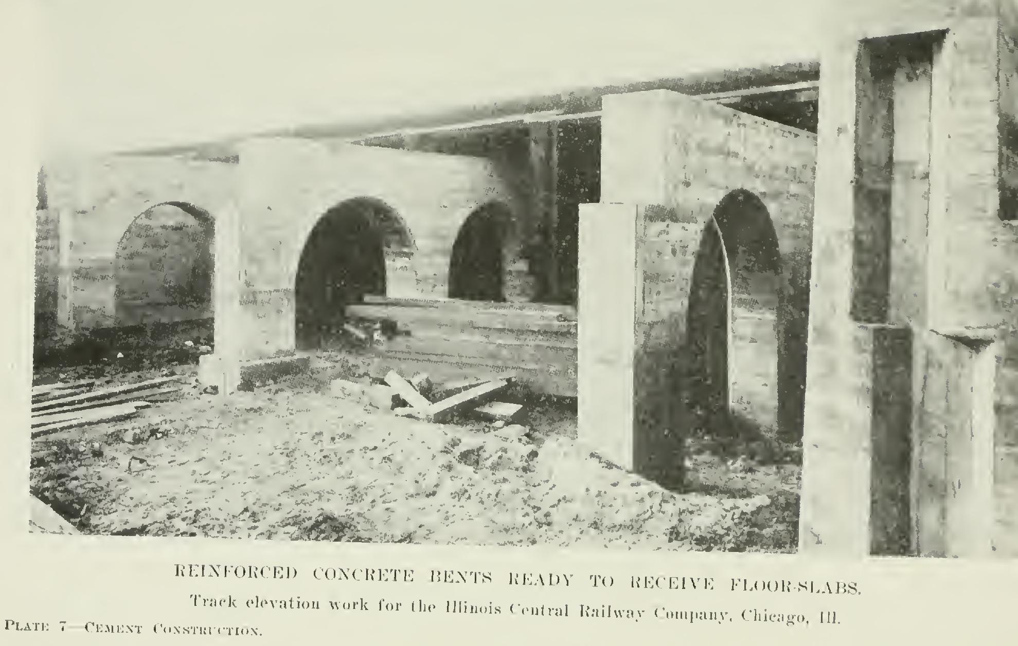
Plate 7 is a view of similar work done for the Illinois Central Railway Company in Chicago.