Placing of Forms
concrete, fig, floor, beams, column, inch and steel
"Fig. 29 is adapted for floors where the concrete is flush or fair with the bottom flanges of the joists, and the latter are any distance not more than six feet apart. Clip hangers made out of steel bars about 1 by inch have a mortise through which iron bars B about by inch are passed; the bars arc fixed three or four feet apart, and inch boards are laid on them to uphold the concrete. The clips are driven on lightly with a hammer. The small wedges are to allow the bar B to be loosened and withdrawn, the boards liberated, and the clips removed.
"The same principle is adopted for roofs where pur lins support the concrete, A (Fig. 30) being the bar. The object of curving the concrete is to lessen the amount and weight of the concrete without reducing the strength.
"Fig. 31 shows an arrangement of forms necessary for beams and floors. The posts should rest on a floor of planks at the bottom, and be placed as far apart as may be necessary. A pair of wedges under each post is necessary, and when released and the 2 by 2-inch wedges withdrawn, the whole of the timber work gives way.

"It is
sometimes the practice to form reinforced con crete beams first, remove the beam forms, erect the floor forms and do the floor concrete as a subsequent process. But this is altogether wrong, as much longer time is required ; and, the floor having to be formed on top of the beams, the latter are deeper than necessary, and possess no additional strength. Where concrete beams are not constructed in place, this arrangement is, however, unavoidable.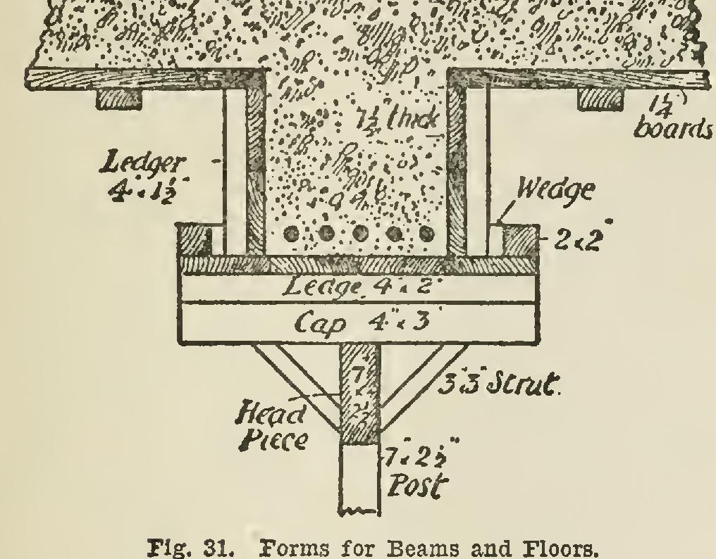
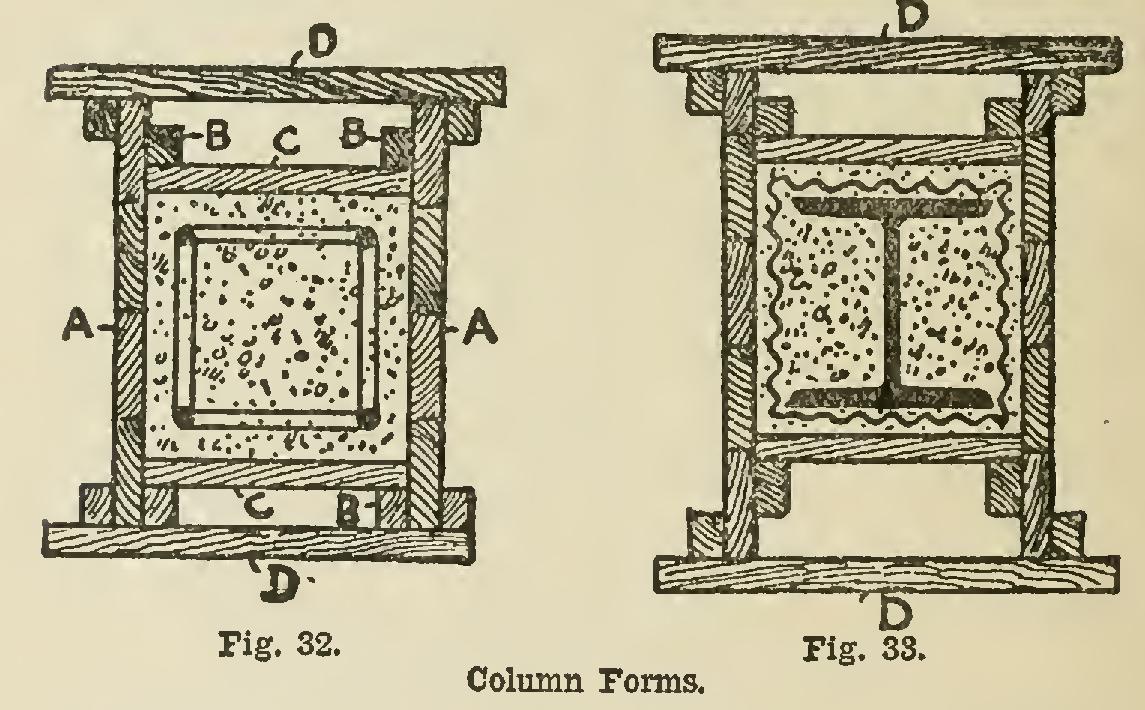
"Forms for concrete columns should be of a substan tial character, or—if of light construction—well and rigidly bound together, as, like water, concrete exercises pressure on all sides. Practitioners differ a good deal in their methods of making forms for columns. My own view for economy and simplicity is shown in Fig. 32, which is a horizontal section of a column form. The sides AA are inches in thickness and strongly ledged together at intervals to prevent the wet concrete from warping and twisting them. They should reach the full height of the column. B B are wood strips or fillets about 2 inches by 1 inch, firmly nailed to A the full height of the form, and each in one piece. C C are boards dropped in singly as the concrete is being deposited in place.
DD are light wood clamps correctly made to keep the sides A A in position. Necessarily the forms require to be strongly stayed to prevent any divergence from the perpendicular. This arrangement can be applied to the encasing of steel stanchions with wire bonds embedded in the concrete as shown in the horizontal section, Fig. 33.
"The sides A A must be watched for alignment ; there is no remedy whatever if they once get out of position and any portion of the concrete has been deposited in place. D D are light wood clamps, made so as to require no wedges. When the concrete is hard, the clamps D D are easily knocked off with a hammer, which releases the form. The woodwork should then be at once cleaned, and is ready for re-use for another column. The principle can be applied to any form or shape column, and to steel stanchions ; and if bond ties are inserted in the concrete at intervals, there is no better way I know of to protect the latter from fire.
"A practical foreman carpenter, possessing common sense, should be quite capable of devising his own forms to suit the numerous requirements of reinforced concrete construction, and possibly better than cut-and-dried rules of instruction. Obviously some slight experience in this direction is an advantage." Regarding the use of steel forms in rein forced concrete construction, Mr. W. L. Caldwell says: forms or centerings for concrete construc tion are the 'bugbear' of all engineers and constructors, not only on account of their first cost, but on account of the great amount of labor and time required to put them to place and remove them after the concrete has hardened. Furthermore, on account of having to re-cut and readjust the centering so many times to complete a modern build ing, it is of little value or use for other similar struc tures—frequently a total loss—and in some cases the contractor must pay for having it hauled from the build ing. The wise and progressive engineers and contractors are endeavoring to find a more suitable and permanent material, less destructible, to take its place, even though the first cost is not so low, a material which can be used over and over again, thereby producing a great saving.