Trestles and Viaducts
concrete, piles, trestle, pile, ft and timber
TRESTLES AND VIADUCTS Railway Trestles. A trestle may be defined as a long bridge made up of a large number of comparatively short spans. There are over 2,000 miles of timber railway trestles in the United States. Some of these trestles will be replaced by earth embankments; but a large part of them carry the tracks over swampy land, flood plains, or city streets, and will have to be maintained indefinitely. The rapid deterioration and large fire risk of a wooden trestle make it extremely desirable to find a more permanent form of construction. A steel trestle is uneconomical for any ordinary height and not very per manent; so reinforced concrete has been sug gested, tried, and proved to be satisfactory in almost every respect. At the present prices, a timber trestle is less expensive in first cost; but with the increasing cost of timber, reinforced concrete will in a comparatively short time have the advantage of cheapness, as it has now of durability, permanence, strength, and stability. In addition to these qualities, concrete trestles are free from maintenance expenses and fire risks.
Fig. 51 shows a side view, top view, and cross section of a typical reinforced concrete railway trestle. This trestle has three spans measuring 16 feet from center to center of piers. The slabs are shown in detail in Figs. 52 and 53; they are 13 feet wide, by 22 inches thick.


A reinforced concrete railroad trestle with concrete pile piers is illustrated in Plate 8. This type of trestle has been found to be rela tively inexpensive, and seems likely to be very extensively used. The following description re fers to the trestles of this kind built by the Chi cago, Burlington & Quincy Railroad: The spans are 14, 15, or 16 ft. long, c. to c. of bents. Each bent consists of six concrete piles handled and driven in the same way as timber piles, supporting a cap or cross-girder which is cast in place. Upon the caps rest the girder slabs which form the floor, each span con sisting of two slabs placed side by side.
The concrete piles are of two forms : (1) rectangular cast piles; (2) Chenoweth rolled piles. The cast or moulded rectangular piles are made to the designs of the Bridge Department. They are made in lengths up to 30 ft., and most of them are not pointed, being 8 by 8 in.
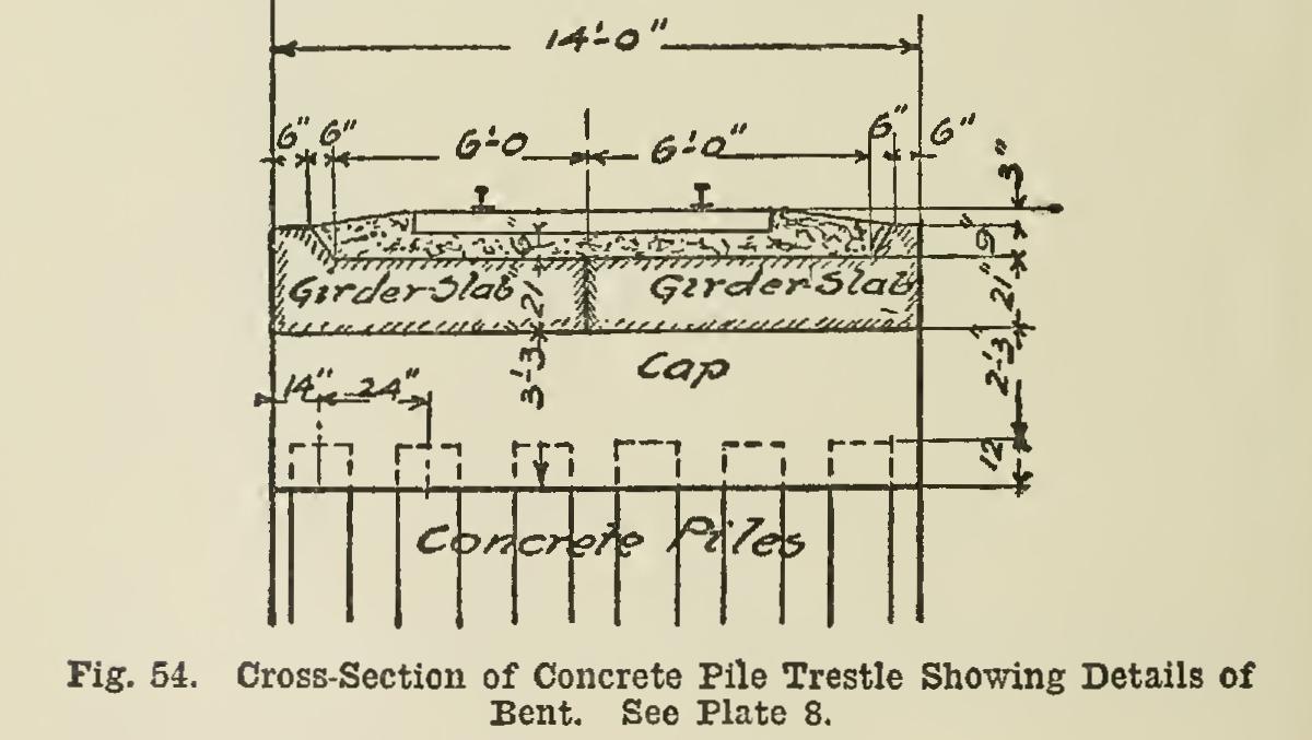
at the smaller end, though some of them have points tapering to 5 by 5 in. The general design of the pile-bents and the construction of the caps, are shown in Fig. 54. The 30-ft. piles are 16 in. square at the top, with 4-in. chamfers. The reinforcement consists of eight bars and a spiral coil of wire of varying pitch. The wire is coiled on a mandrel. When the coil is completed, it is removed and set in place in the form, the longitudinal rods being wired to it at intervals. Each 30-ft. pile con tains: 1.044 cu. yds. of concrete ; eight steel bars in. square and 29 ft. 6 in. long; and 535 ft. of No. 12 black wire.
The Chenoweth rolled concrete pile has a reinforce ment consisting of a spiral sheet of netting, with the usual longitudinal bars.
In the construction of the trestle, the piles (whether of the cast or rolled patterns) are driven by a railway pile-driver in the usual way. A cushioned cap is used in driving, and there has been very little trouble from break age of the piles. When breakage has occurred, it has been due, as a rule, to using a pile which has not been given sufficient time for thorough setting or seasoning of the concrete.
The cost of driving is found to be a little higher for concrete piles than for wooden piles. Where possible, a water-jet has been used, making the driving of the pile very much easier and more economical.
The piles being driven, a form is built for the cap of each bent. This has a sheet-iron lining. The corners are chamfered, and the ends of the caps are rounded. The concrete is well-spaded at the sides of the form to give a smooth surface. The forms are left in place about 30 days, before the superstructure is set in place.