Hot-Air Heating
floor, register, pipe, air, inches, registers and fig
A simpler rule, quite accurate in the results obtained, is to allow one square inch of grate area in the furnace for each 40 actual cubic feet of contents, if the house to be heated is well constructed and is exposed on all sides. If part of a double structure, or one of a row of houses, use the number 50 as the divisor.
The house illustrated in Figs. 1, 2, and 3 has slightly more than 15,000 actual cubic feet to be warmed, and is an isolated structure. Therefore, 15,000÷40.375 square inches of grate surface required. This would call for a grate approximately 22 inches in diameter (a circle 22 inches in diameter gives an area of 380.13 sq. in., or slightly more than necessary).

Location and Size of Registers and Flues. Registers should be located along or in the inner walls of each room. The dotted lines dividing the floor space of the various rooms in Figs. 2 and 3, explain this. The registers should be placed inside the dotted lines. Formerly it was considered good practice to use floor registers for all first-floor rooms, and wall registers for the rooms above the first floor. However, the recent introduction of the improved side-wall register, Fig. 4, has changed this former idea. By the use of this type of register in a three or four-inch wall, an opening for a flue at least 7 inches deep is obtained by cutting out 2 inches of the floor. This, together with the space of 1 inch occupied by lath and plaster, gives a flue 3 inches deeper than the studding, and allows the placing of an effective register for warming first-floor rooms. In a similar manner a single flue can also be made to heat a first and a second floor room, thus simplifying the piping system and lessening the number of pipes in the cellar.
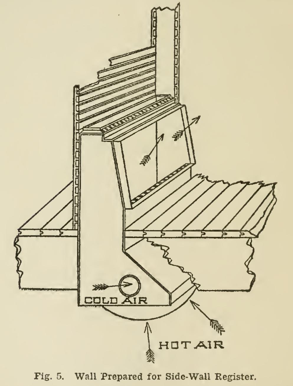
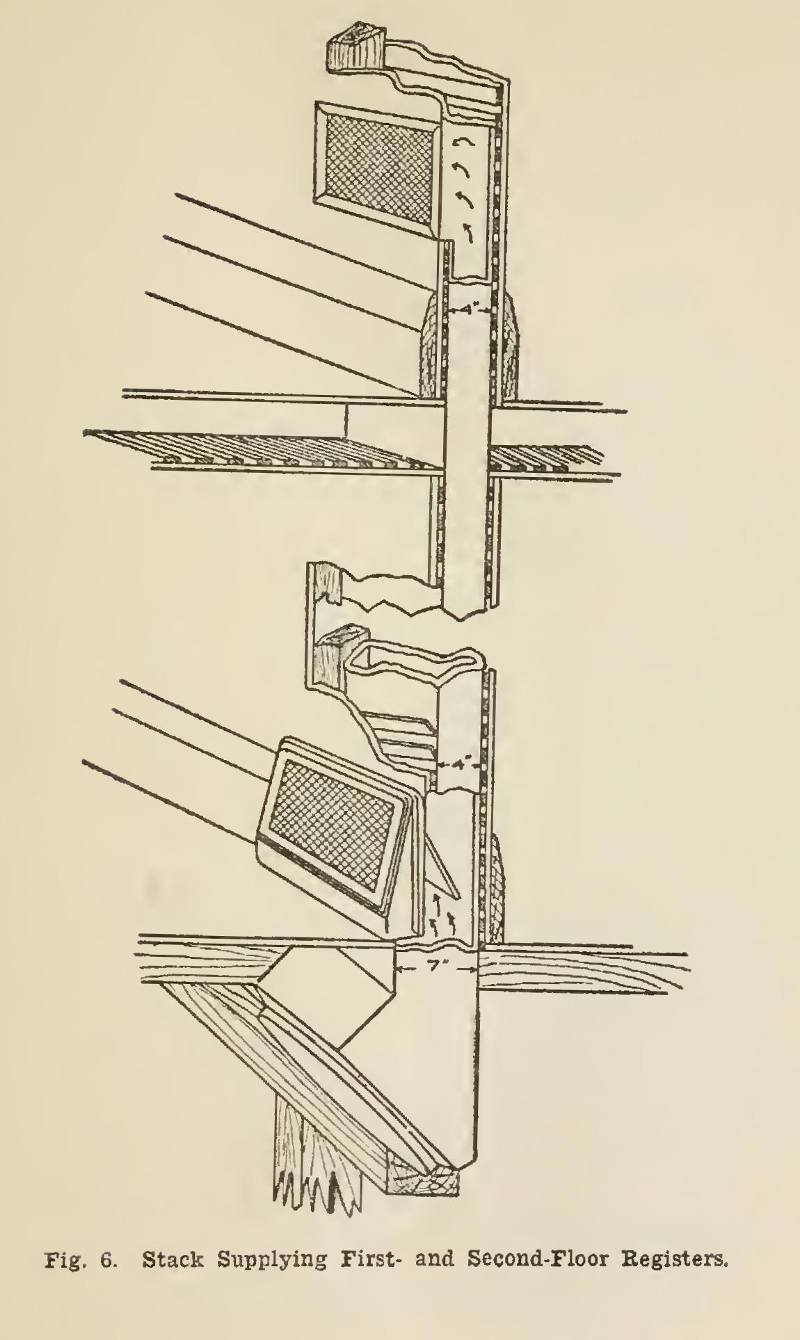
There is much to be said derogatory to the use of the floor register. It is a dust and dirt collector; it frequently interferes with the desired placing of furniture and often necessi tates the cutting of carpets. All these adverse conditions are obviated by using the side-wall register. Fig. 5 shows the wall prepared and the opening cased ready for the insertion of the cast-iron register frame. Fig. 6 shows a stack supplying the first and second floor registers. Note that by this arrangement, as cited above, the depth of the flue supplying the first floor is 7 inches. A baffle-plate divides the flow of
warm air, furnishing each floor with its proper proportion of heat.
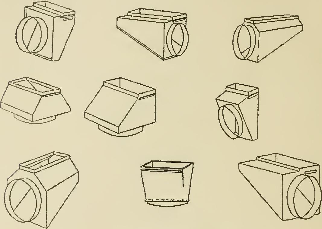
The fitting at the bottom of a stack, or verti cal duct, supplying a register, is termed a boot. The round pipe in basement conveying hot air from the furnace is connected to a boot, which must be so arranged as to receive the full vol ume of this round pipe and distribute it to the riser with the least possible amount of friction.
A variety of designs are therefore necessary to answer suitably certain requirements, and Fig. 7 shows a number of correct forms.
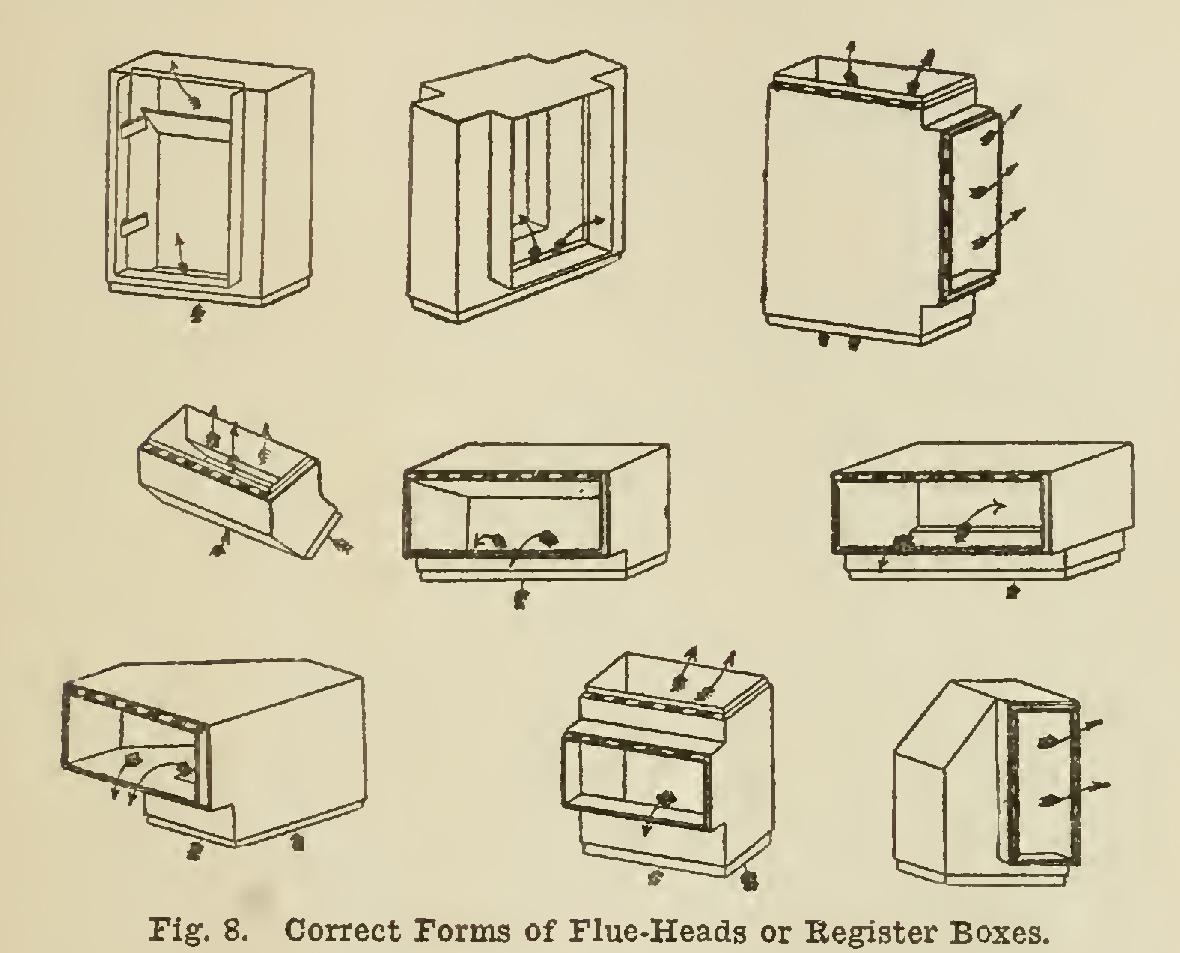
The fitting at the top of a riser or flue is termed a flue-head or register box. These are made in a form to supply a single register, or they may be so arranged as to be suitable for supplying registers on opposite sides of the partition. Fig. 8 illustrates some correct forms of this fitting.
In the running of all furnace piping, abrupt bends and acute angles should be avoided, so that the heat-carrying pipes may offer the least possible amount of, friction or resistance to the flow of warm air through them.
hot-air pipes should be covered with asbestos paper, or, better, with asbestos air-cell covering. Should circumstances require the placing of a pipe within an outside wall, its outer surface should be doubly covered in a permanent manner with first-class material. Asbestos air-cell covering also affords a pro tection against fire liable to be caused by an overheated pipe.
In this connection it is advisable to call attention to a new type of furnace piping, as illustrated in Fig. 9. The design is called Safety Pipe, and is of double construction with an air space between the two layers of metal. A small opening through the outer pipe in the boot admits cellar air.
Table I will give the measurements of regis ters necessary for supplying certain sizes of rooms, the sizes of flues (vertical pipes), and the sizes of the round pipe in the basement convey ing warm air from the furnace to the boot. In a11 cases where two or more rooms are heated from one pipe, this pipe must have sufficient capacity to carry the required amount of warm air for all rooms serv ed by it, according to the information given in the table.