Hot-Water Heating
system, size, radiation, steam, flow, heater and supply
In view of the above information, it is im possible to give too much care and attention to the usage of the various forms for connecting and venting the expansion tank and the radi ators on a system of hot-water heating.
To estimate the amount of direct hot-water radiation required to heat a building properly, proceed exactly in the manner already described for determining the quantity of radiation neces sary for steam heating; and to the result ob tained according to that rule, add 60 per cent. For example, suppose we find that 450 square feet of steam radiation would be required on the installation. Then, 60 per cent of 450 is 450 X .60=270. Adding this to the 450, we have 450+270=720. That is, 720 square feet of di rect hot-water radiation will be needed to do the same work.
When providing for indirect radiation in hot-water heating work, it is necessary to figure still stronger in proportion than on a steam job, and 75 per cent should be added to the amount of direct steam radiation in order to determine the square feet of indirect hot-water radiation required to do the same work.
To calculate the size of heater required for hot water, proceed in exactly the same manner as before described for determining size of steam boiler.
Note that for a steam-heating plant we use the term "Boiler" to designate the source of heat supply, as distinguished from the term "Heater" for a hot-water apparatus. The dis tinction is made because of the fact that in gen erating steam we must "boil" the water; while for hot-water heating we do not boil the supply, but simply "heat" it.
Two-Pipe System.
The two-pipe or double main system is the ordinary or common style of piping adopted for hot-water heating. It is the oldest of the several methods to-day in general use; and notwithstanding the fact that many new ideas in hot-water circulation have been evolved from time to time, the two-pipe system is still the most favored plan of piping practiced on a hot-water job.
New ideas applied in the installation of this system, including revised methods of making the various pipe connections, have vastly improved its operation. Some years ago it was the gen eral custom, when erecting such work, to use a large number of flow pipes—one independent supply to each group of radiators, with a cor responding separate return pipe—with the re sult that frequently as many as ten or twelve or 2-inch flow and return pipes were run on a residence job of ordinary size.
Experience has shown that the amount of friction in one large pipe is much less than that encountered in the number of small pipes neces sary to afford the same area; and as a result, we now seldom use more than two flow pipes of the proper size on a job of average proportions. To get the best service from a given amount of fuel, it is necessary that friction in circulation be reduced to a minimum.

The flow pipe or pipes are started at a point above the heater, from such a height as will allow of an upward pitch to the main or mains to the extreme end of the system. The degree of this pitch should approximate one inch for each ten feet of length; and each branch from the main should pitch up from the main one inch in each five feet of length. Each flow pipe when starting from the heater is of a size sufficient to feed all of the branches supplied by it; and each such supply is gradually reduced in size as the various branches are connected, until, at the end of the line, it is but one size larger than the riser or radiator connection which it feeds.
Fig. 37 is an elevation of a two-pipe system. The main flow and returns are run parallel to one another, with a sufficient distance between the pipes to admit of applying pipe covering. The branches, as a rule, are taken from the main by the use of the 45-degree connection, in the same manner as for one-pipe steam work, although, when a branch supplies only upper floor radiators, it is good practice to take the line from the side of the main. As a rule, the return branches should be connected into the side of the main return.
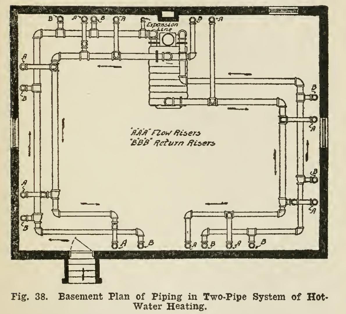
It was a former practice of many fitters to take the branches from the top of the main; but, since each direct right-angle turn as afforded by a 90-degree elbow and top main connection in creases the friction in the circulation, this method has been largely discontinued. The gen eral view of this system shown in the basement plan of piping, Fig. 38, will possibly prove more clearly illustrative of the system. The course of the circulation is indicated by the arrows, which show the supply of hot water from the heater flowing towards the radiators, and the cooler return water flowing back to the heater to be reheated.