Hot-Water Heating
tank, water, fig, system, riser, expansion and radiator
Heating engineers are agreed on the point that the hotter the water when it returns to the heater, the more quickly the supply is reheated and again put in circulation through the flow pipes. Therefore, to the owner, this heated con dition of the return water affords increased effi ciency and economy in comparison with an ap paratus in which, owing to a poor arrangement of piping, the flow is so retarded as effectually to cool the water while traversing the system.
As water is heated from 40° to 212° it ex pands, gradually becoming more bulky, the degree of expansion approximating one twenty fifth of its volume. When used for heating, it is necessary to provide some means whereby the supply may freely expand and contract without admitting air to the system. To provide for this condition, a small tank, called an expan sion tank, is used, in which the water may rise and fall without in any way interfering with the heating system. This receptacle should be located at a point not less than three feet above the top of the highest radiator, and it may be connected to the return pipe from one of these highest radiators, or directly into the return at the heater. The pipe connection from the tank to the apparatus is called the expansion pipe or expansion line. A vent pipe, which is usually taken through the roof of the building, must also be carried from the top of the tank to the atmosphere, this outlet providing a necessary overflow.
Expansion Tank Connections. Of the three distinct methods of connecting the tank, Fig. 29 shows the one most commonly adopted. This WE method does not provide for the warming or the circulating of the water in the tank; and there fore, when this type of connection is used, it is always advisable to place the tank in a warm room or protected position, in order to prevent freezing and a consequent sealing of the system, which might result in the generation of an exces sive pressure likely to cause an explosion or similar injury to the plant.

Fig. 40 shows the method practiced for cir culating the hot water to the tank, this connec tion being employed when the expansion pipe runs through a cold wall or room, with a conse quent liability to freezing.
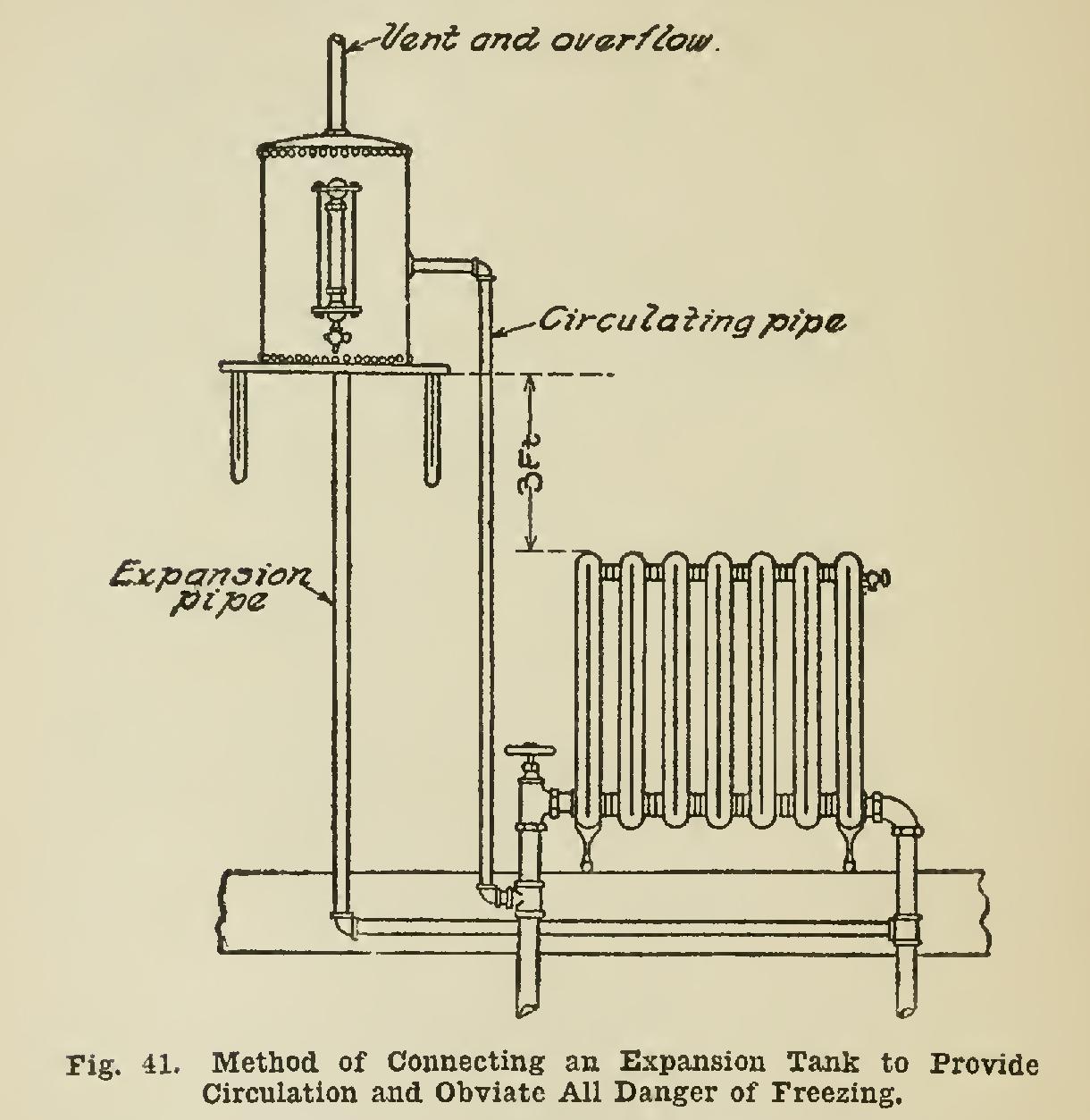
When it is necessary to place the tank in a cold spot, some provision should always be made for circulating the water within it. One method
of accomplishing this result is illustrated in Fig.
41. A tank connected in this manner has no possible chance of freezing.
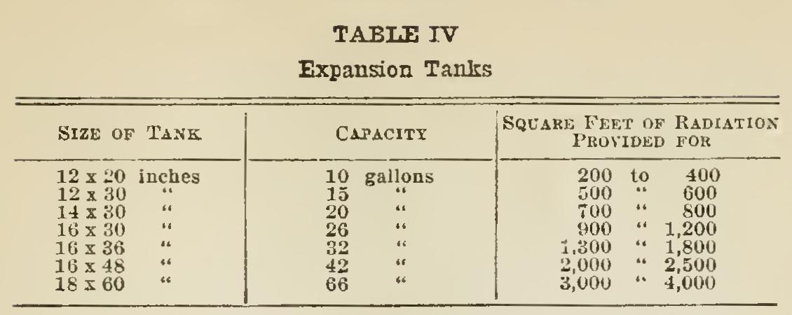
Expansion tanks are made in certain stand ard sizes. Table IV shows the sizes and capaci ties of different tanks and the proper size to use for certain specified work.
Frequently it is desired to arrange the ap paratus so that hot water may be drawn from the system in an advantageous manner. In such a case, if the regular form of tank were used, there would be danger of lowering the water below the top of the highest radiators, thus admitting air and blocking the circulation. To provide a suitable arrangement whereby a supply of hot water can be frequently drained from the system without suffering the above dis advantage, an automatic tank of the type shown in Fig. 42 should be attached to the plant. The water supply to this tank is controlled by a ball cock and float, which in operation admit water to the system as rapidly as any quantity is drawn from it, the action being quite similar to that of the ordinary closet tank. No water-gauge is re quired on a tank of this character; and as the top is open, a vent is not necessary.


Hot - Water Radiator Connections. The usage of the double-swing or expansion joint, to which attention was called in discussing the con nection for steam radiators, is not necessary in connecting a hot-water radiator; in fact, this type of connection is harmful, owing to the in creased friction caused by the employment of the extra elbows. Fig. 43 shows the ordinary method of joining a hot-water radiator to the flow and return mains, this connection being made in as direct a manner as possible.

When a branch feeds a first-floor radiator and a riser, the connection is made as shown in Fig. 44.
Where a second-floor radiator and a riser to floor above are connected, the third-floor riser is taken from the side of the one supplying the second-floor surface, as illustrated iu Fig. 45. Note the application of the reducing tees on the riser.
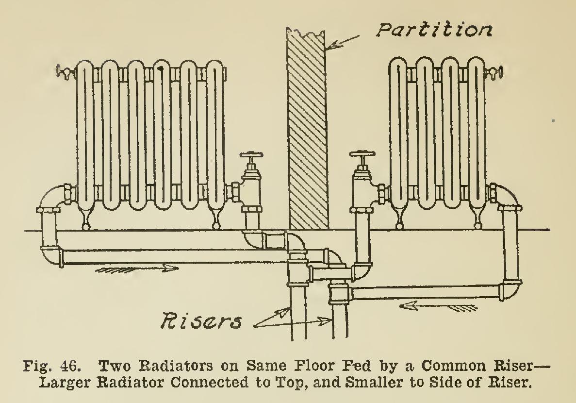

When two radiators on the same floor are fed by a riser, the larger one should be supplied from the top of the riser, and the smaller radi ator from the side of the riser, as shown in Fig. 46.
