Hydraulic Rams
valve, water, head, pressure, air, drive-pipe and air-chamber
HYDRAULIC RAMS Hydraulic rams form a convenient and inex pensive method of delivering water from a lower to a higher point, and, after the first cost of installation, require very little expenditure for repairs, and require very little attention, as they work automatically.
A section of a so-called double-acting or double-supply type of hydraulic ram, is shown in Fig. 113. Considering it first without regard to the double-acting feature, suppose the open ing at H to be closed. The valve at B being open, the water from the source of supply at more or less elevation above the machine flows down the drive-pipe A, and escapes through the opening at B, until the pressure due to the increasing velocity of the water is sufficient to close the valve B. At the moment when the flow through this valve ceases, the inertia of the moving col umn of water produces the so-called ramming stroke, which opens the valve at C, and com presses the air in the air-chamber D until the pressure of the air, plus the pressure due to the head of the water in the main, is sufficient to overcome the inertia of the moving column of water in the drive-pipe. This motion may be likened to the oscillations in a U-tube. At this instant the column of water in the drive pipe has come to a rest; and the air-pres sure being greater than the static head alone, the direction of motion of the moving column is reversed, and the valve C closed. The water in the drive-pipe is then moving backward; and, with the closing of the valve C, a tendency to a vacuum is produced at the base of the drive pipe; this negative pressure causes the valve B to open again, completing the cycle of opera tions. At the moment of negative pressure, the little sniffing valve E admits a small quantity of air; and at the following stroke, this passes into the air-chamber, which would otherwise fill with water gradually, the air being slowly taken up by water. In many machines, the mistake is made of making the waste-valve B sufficiently heavy to overcome the static head of water in the drive-pipe. In fact, most writers on this subject state that the weight of the waste valve B must be greater than the pressure of the static head of water on its under side, so that it may open when the column of water comes to rest.

In the machine above described and illus trated in the accompanying figures, this would be practically impossible, on account of the large area of the opening at B.
In this machine—known as the "Rife" hy draulic rain—the valve B is made as light as is consistent with the necessary strength, the nega tive pressure at the end of the stroke is relied upon to open the valve. With the largest sizes of these machines, this valve is 18 inches in diameter, and, with a head of 8 feet, which is a common head for use with hydraulic rams, the static pressure on the under side of this valve is 883 pounds; it can very easily be seen that the great shock of a valve of this weight would rap idly destroy the valve and its seat.
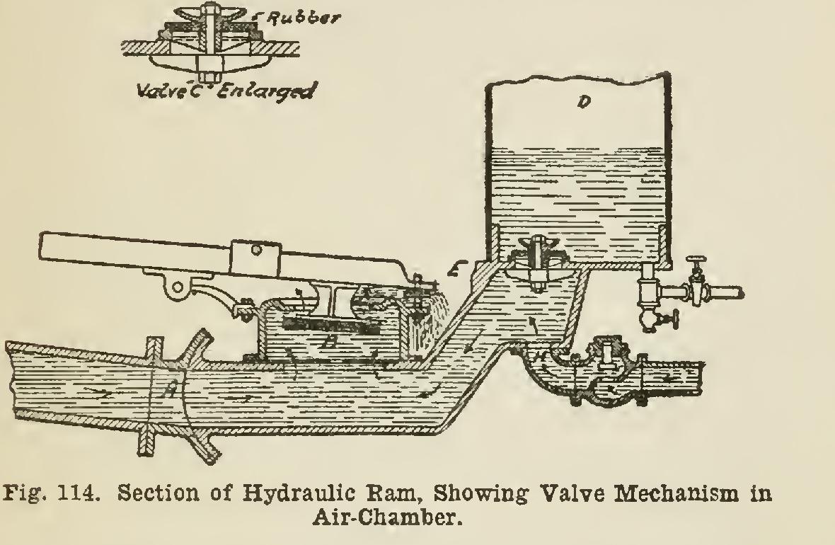
The waste mechanism consists of a large port with a flat, ample opening; and a large rubber valve with a balance counterweight and spring seating, Removing almost entirely the jar at closing. The valve C in the air-chamber con sists of a rubber disc with gridiron ports and convex seats, fastened at the center and lifting at the circumference, as shown in Fig. 114. The effort is to transfer the shock from the power of the driving water through the air-cushion, with the smallest amount of friction and jar.
After the closing of the valve C, the pregsure of the air in the air-chamber forces the water in the air-chamber out into the delivery pipes. It is claimed that water can be elevated as high as thirty feet for every foot of fall in the driving head.
To the reader who has carefully followed the above description, it will be clear that the most important detail in which the type of hydraulic ram here described differs from the ordinary hy draulic ram, is the waste valve. The counter weight on the projecting arm of this valve per mits the adjustment of the valve to suit vary ing heads and lengths of drive-pipe. By adjust ing the counterweight so that the valve is nearly balanced, the valve comes to its seat very quickly after the flow past it begins. The result is that the ram makes a great number of short, quick strokes which are much easier on the mechanism than slower and heavier strokes. Of course the stroke must be sufficiently powerful to act effi ciently in overcoming the head in the delivery pipe. The adjustable weight permits this to be effected with the greatest nicety.