Windows in Frame Walls
fig, section, window, sill, sash and ground
WINDOWS IN FRAME WALLS Plate XIV illustrates the construction of a double hung sash window in a frame wall. It is what is known as a skeleton frame without a ground casing, and is the kind of window frame that is used in the cheapest grade of work.
Principal among its weak constructive features are the omission of grounds to nail trim to, the use of a single sill instead of a sill and sub-sill and the omission of a ground casing, without which a true pulley stile cannot be insured.
Fig. 71 is a section through the head.
Fig. 72 is a section through the jamb.
Fig. 73 is a section through the sill.
Fig. 74 is an isometric view of head.
Fig. 75 is an isometric view of jamb and sill.
Plates XV and XVI continue the illustration of double hung sash windows in frame walls. The first plate illustrates a skeleton frame with a ground casing.
Fig. 76 is a section through the window head and could be improved by the use of grounds nailed to studs to serve as a gauge for plastering and as a nailing for the trim. The tops of all windows on exterior are almost always exposed to the weather and, as indicated in this case, should be well flashed with tin or copper.
Fig. 77 shows a section through the meeting rails.
Fig. 78 is a section through the jamb of the window and shows the ground casing, marked "G C." When grounds and ground casings are omitted, the trim must always be wide enough to get a nailing into the studs. The outside archi Crave should always be at least one and one-eighth inches thick or better, one and three-eighths inches, to receive clapboards or shingles.

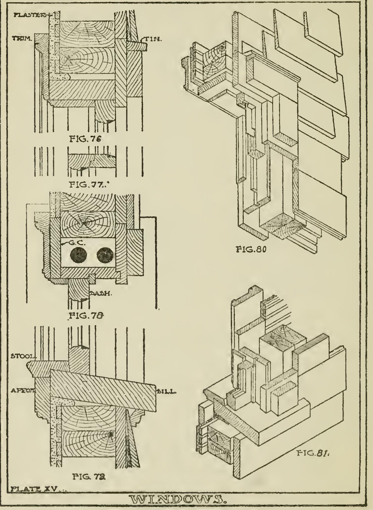
Fig. 79 is a section through the sill of the win dow. The openings around sills and heads of windows should always be plastered up with "scratch" mortar, as shown.
Figs. SO and 81 are isometric views of the pre vious sections.
Plate XVI illustrates a somewhat better meth od of constructing the window frame and shows how a mosquito screen may be put on outside of sash.
Fig. 82 is a section through the head and shows the use of grounds, marked "G." The inside
finish is more elaborate than in the preceding examples.
Fig. 83 shows the sliding mosquito screen on outside of sash. The running strip is nailed to the outside casing.
Fig. S4 is a section through the sill and shows the bottom rail of mosquito frame and the ground, marked "G." Also, instead of a single sill, as is used in cheaper work, a sill and sub-sill are pro vided, same being put together in white lead. The groove or water nose on bottom rail of sash pre vents water from entering under same.
Fig. 85 is an elevation showing the inside finish around window.
We will consider two special methods of con= structing double hung sash windows. The first, shown in illustrations on Plate XVII, is a window so constructed as to permit the use of mosquito screen, and blinds with swivel slats outside of the sashes. This is accomplished by putting the out side casing "D," over the sheathing boards "C," which makes a wider box for sash weights and allows the piece "A" to be set for mosquito screen. The space between mosquito screen and blind "B" is required for blind fasteners.
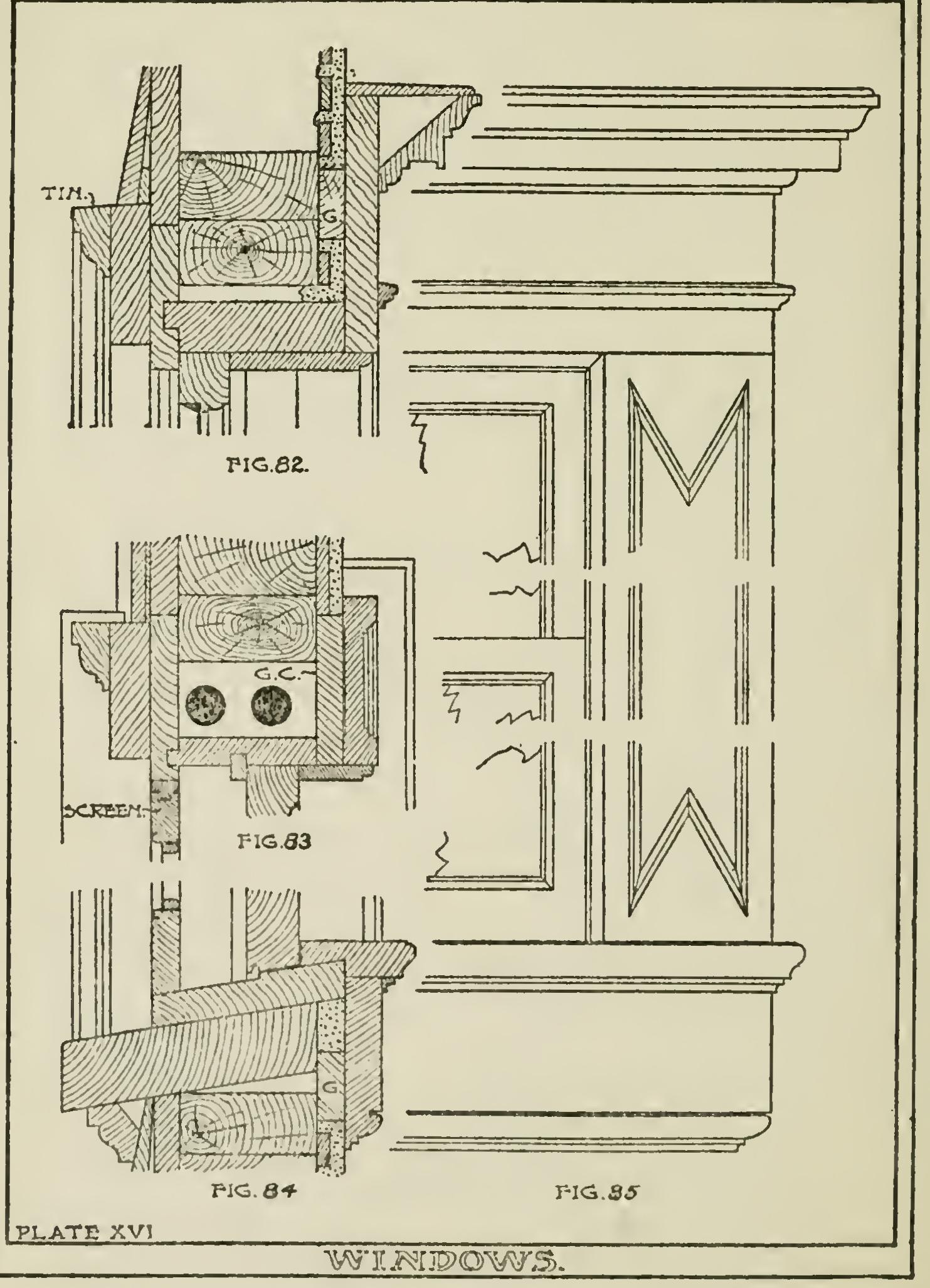
Fig. 86 is a section through the window head.
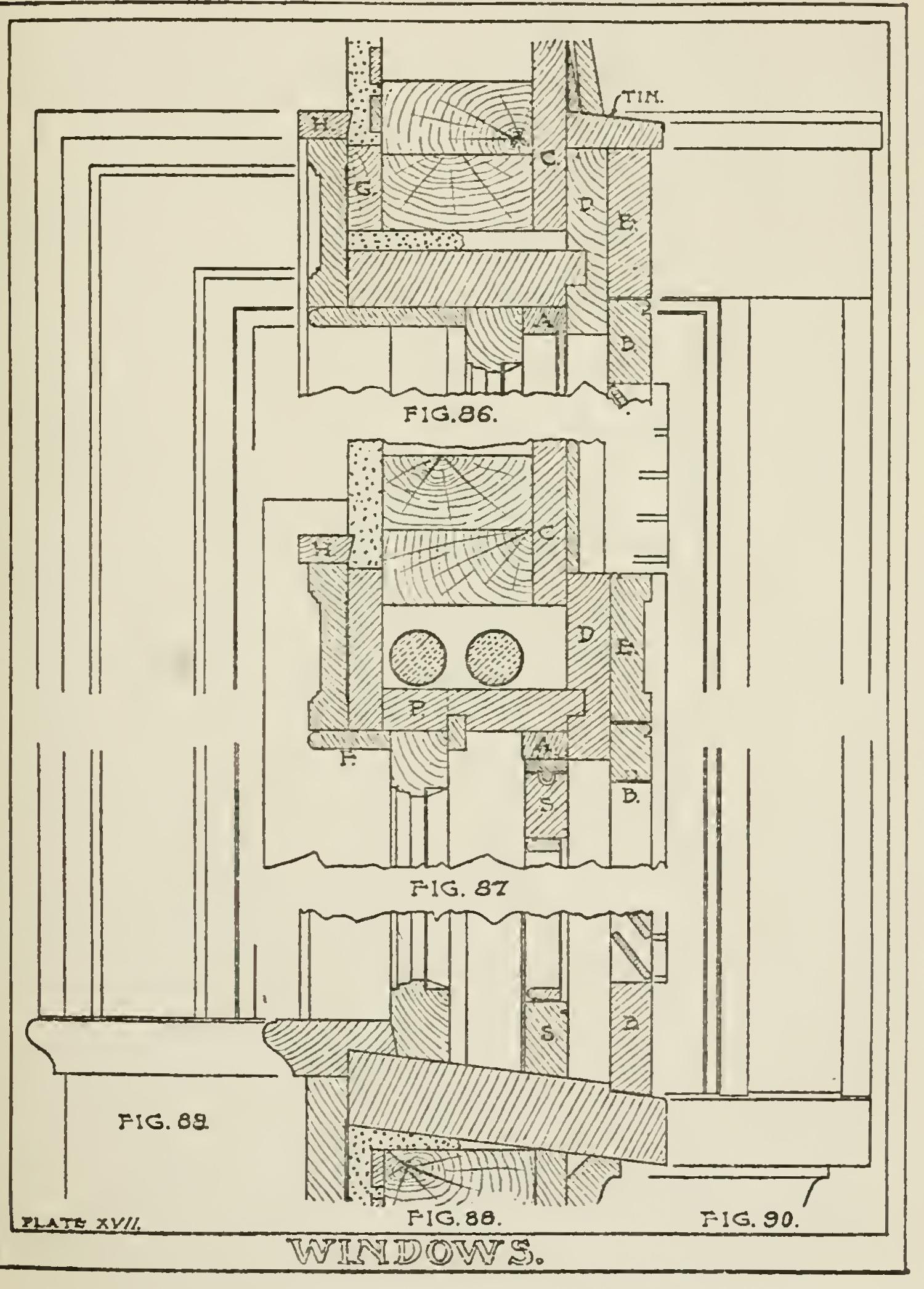
The ground "G" serves as a gauge for plastering and as a nailing for the trim and should always be used in the best work.
Fig. 87 is a section through the jamb of the window. The stop bead "F" should never be less than one and three-fourths inches wide so as to allow proper space for the window shades. At "P" a pocket is formed in pulley style for access to sash weights.
Fig. 88 is a section through the sill of the win dow. The sill should be grooved out three-eighths of an inch for pulley stile.
In all good work a back mould "H" should always be provided. This mould has a beveled edge which may be planed off to fit the unevenness of the plaster work.
Figs. 89 and 90 are respectively interior and exterior elevations of the window.
Plate XVIII illustrates a somewhat better method of construction than any previously shown.