Hip Roof Framing
degrees, square, line, rise, shown, angle and run
Reckoning by Degrees.—Angles are formed by the divisions of the circle, called degrees, of which it contains 360, and these parts are again divided into 60 parts, called minutes, and these parts are again divided into 60 parts, called seconds. From this it will be seen that there are many fractional parts, and if used for the pitches would result in fractions in the lineal measurement of the rise given the roof. Only the 45 degree is without a fraction on the blade of the square when using 12 on the tongue. Besides, there is no way of arriving at the meas urement of same without a problem of no small means in trigonometry or the use of a protractor to arrive at the desired angle from which to take the measurements by scale.
In looking up the subject we fail to find pitch as applied to the roof defined in any of the encylo pedias other than by the degrees given the incline of the roof. Therefore, it is more than probable, to avoid these troublesome fractions, custom has settled on taking a proportion of the span for the rise. Thus, knowing the measurements of two of the factors (run and rise), the third (pitch) is easily arrived at by scale and from their measurements, the various angles for the cuts may be obtained with the steel square with out the knowledge of the degrees entering into the problem.
Table of Decimal Equivalents.—In connection with this illustration we also give in Fig. 49a, a table of decimal equivalents to the one-twenty fourth part of an inch for convenience in finding their value in common fractions.
Framing by Degrees.—The following is copied from an article by Mr. Woods published in a trade paper and will be found useful in this line of work.
In some sections of the country with many framers, the rise is reckoned by the degree in stead of a rise in proportion to the span. The rules in the application of the square for the cuts and bevels remaining the same, but in degree framing it requires a trigonometric formula, or a protractor, to determine the rise. In the ab sence of the protractor one may be temporarily devised as shown in Fig. 50, as follows : Lay off an angle of 90 degrees, which may be done by marking from the heel of the square along both the blade and tongue. The square, we will say, being in the position of No. 1, and with the angle as center lay off a quarter circle, the radius of which may be any size desired, the larger the more accurate will be the result.
Now reverse the square, as shown by the square No. 2, and with the 12-inch mark on the tongue resting at the heel or angle of square No. 1. A line from 12 to 12 will bisect the quarter circle at an angle of 45 degrees. Now with a pair of spacers divide the arcs thus formed into nine spaces, which will make the divisions five degrees apart, and by dividing these spaces into five equal parts will give the division of the degrees. However, it is only necessary to divide that section containing the desired degree. If it be 52 degrees then we divide the space above 50 degrees, as shown, and a line from 12 on the tongue and passing at 52 degrees will intersect the blade at 151 inches and represent the rise per foot in the run.

In Fig. 51 is shown a diagram of how to find the lengths of the rafters to a given scale, also the bevels that give the cuts. The square may be applied to the angles instead of the bevels, if desired.
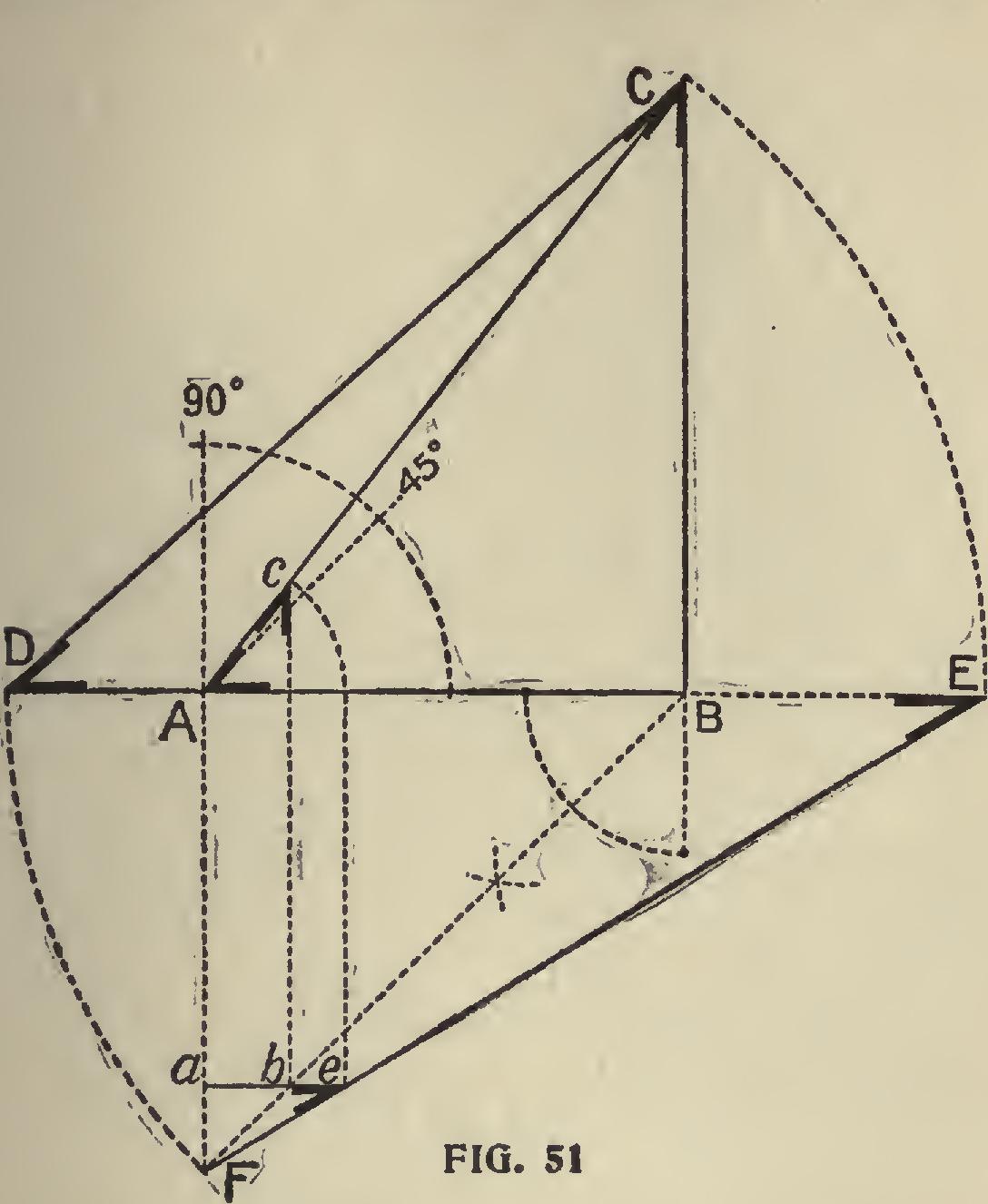
Without going further into the details of the construction of this diagram we will give the different parts as follows: Let AB represent the run or seat of the com mon rafter, and with A as center lay off the arc and proceed as in Fig. 50 for the pitch. BC will represent the rise, AC the length of the common rafter, BF the seat or run of the hip (this line always rests at an angle of 45 degrees with AB, unless the adjoining sides of the roof are of a different pitch), and equals DB. DC represents the length of the hip and equals FE, the latter being drawn to obtain the bevels for the cuts. AE is obtained by dropping AC on a line with AB.
a, b represents the run of the first jack from the corner, and by squaring up to AC, as shown, its length will be Ac, and represents the common difference in the lengths of the jacks. The seat and down bevels remain the same as for the com mon rafter, but require an additional bevel across the back to obtain the cut to fit against the hip. This is found by extending ab, intersecting FE, as shown, at e.
It will be seen that ae equals Ac, and may, therefore, be taken for the length of the jack.
For the backing of the hip, lay off one-half of its (the hip's) thickness from D on line DB (seat cut) will give the gauge line or the amount to remove to a center line at top of the hip.