Possibilities of the Steel Square
shown, line, degrees, desired, polygons, miter, figures, blade and triangle
In Fig. 122 is shown another way of handling the steel square in laying out the polygons. Here we show two squares as though they were pivoted at 12 on the tongue and made to work like a pair of shears. Just above this is shown the semi circle with its 180-degree divisions also centering at 12. The degrees are read from the top each way and are to the steel square as the dial to the weighing scales. Thus, to find the side of an octagon, divide 180 by 8, equals 22/. Now swing the blades up until the tongues are in lines with 22/ degrees and the angle formed by the blades will be that of the octagon corner as shown in the illustration, 12 and the figures at the intersection of the blades (4 23-24) will give the required miter. The blade giving the cut. By laying off the desired circumscribed radius on a line directly below the intersection of the blades and where the circle intersects the line of the blade as from 4 23-24 to A will be the length of the desired sides. The quotient for the square, or tetragon, is 45, and that for the triangle is 60 degrees, as shown. For effect in the illustration, we have used one common center for the above polygons. The dotted lines represent the space over which the steel square would travel in laying out these polygons. By using the same center, the penta gon, hexagon and heptagon would come in their order between the tetragon or square and octagon, and continue on as the number of sides is in creased in the polygon.
We have one more illustration along this line we wish to present, as shown in Fig. 123. In this we show four of the polygons beginning with the triangle and developed with the aid of the steel square from a straight line. The application of the squares is shown for the triangle and hexagon with the figures given for the square and pentagon.

Now just suppose the tongues of the steel square are pivoted at 12 to the line as shown. Now by raising the blade up until the figures on the one that give the miter, intersects the straight line, the angle formed by the tongues will be that of the corresponding polygon. According to the illus tration the sides of all of the polygons are 24 inches in length, though they could be by this method laid out to any desired length and by squaring out from the sides at one-half of the desired length and the intersection of these lines will be the center of the desired polygon.
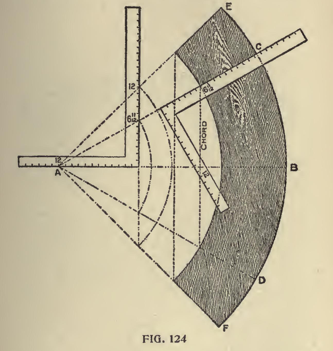
Laying Out a Circular Frame.—In Fig. 124, is shown how any part of a circular frame may be laid out with the aid of the steel square. If we wish to lay out one-sixth of the frame, it may be done as follows : Lay off the desired radius as from A to B then apply the square with the 12-inch mark at A as shown and draw a line from 12 on the tongue, passing at 6 11-12 inches on the blade and drop to an equal amount on a plumb line below the heel, then that part of the frame as from C to D will represent one of the desired pieces, and by applying the square to the chord line, as shown, will give the required miter. Proceed in like man
ner for four pieces, using 12 on the blade and the space from E to F will be one of the desired pieces. The space from C to B represents one-twelfth and from E to B, one-eighth of the complete circle, but since the chords are changed, it requires the figures on the square that give the miters for the respective polygons.
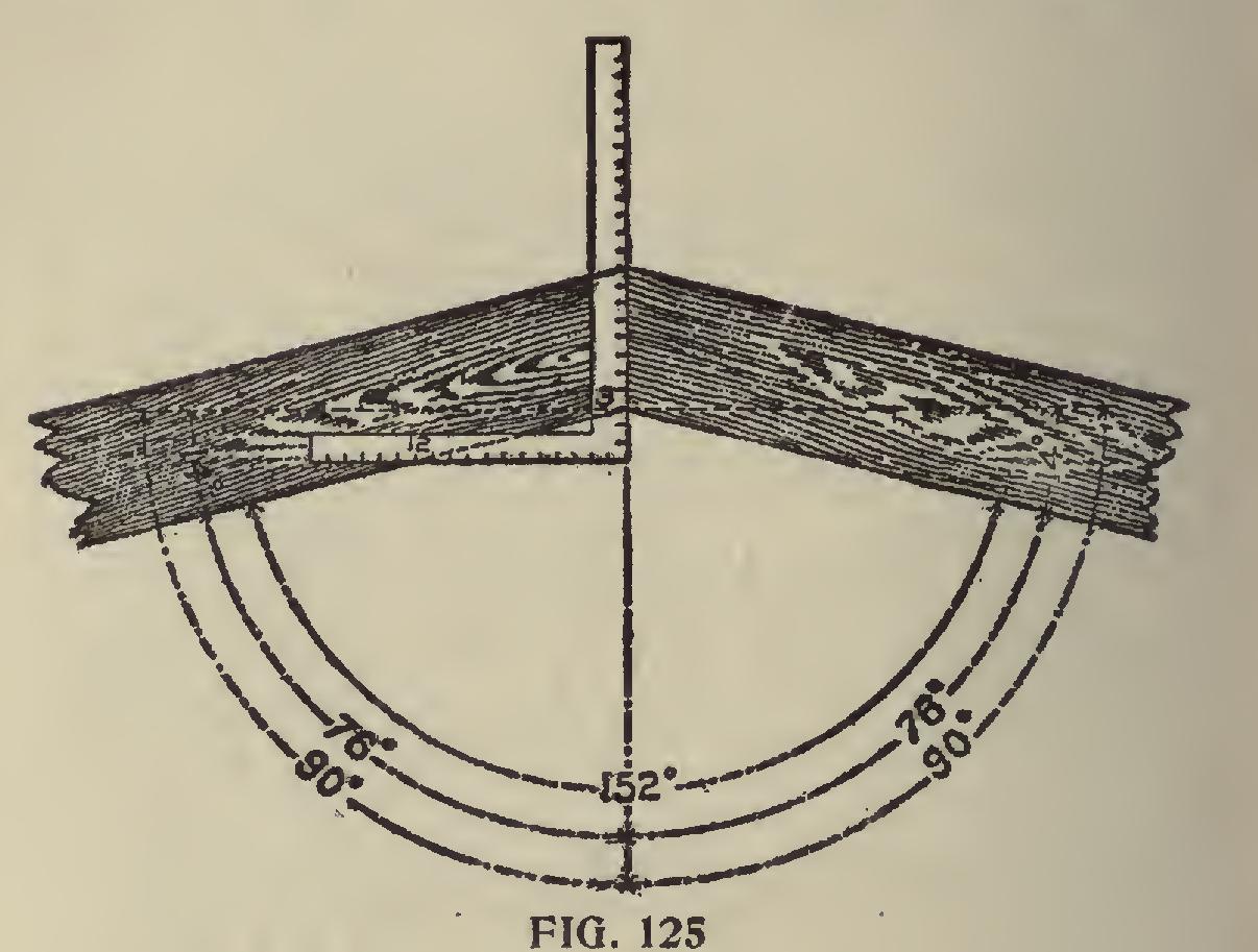
Framing to Any Degree.—In Fig. 125 is shown how to frame to any degree. For an example, say we wish to frame two pieces at an angle of 152 degrees. It is evident that the miter should stand at half way between the angle, or at 76 degrees from either side, and 76 degrees from 90 degrees leaves 14 degrees. We find the tangent for 14 degrees to be 2.99 or practically, 3 inches. Therefore, 12 on the tongue and 3 inches on the blade will give the miter, the latter giving the cut. The square s placed would give the cuts for a brace set to either 14 or 76 degrees.
Ornamental Figures in Miter Work. We
will now call the attention of the reader to a few ornamental figures in miter work that may be accomplished by the aid of the compass and steel square. In this there is a wide field for culture with practically no end. We have prepared for this work a few designs along this line and the mechanically inclined will find in these excellent practice and if he has an eye for designing, these also will furnish a nucleus upon which to plan other designs that will not only give practice and perfection in handling the steel square, but will help to broaden his knowledge in its use and place him on a higher plane in his chosen profes sion.
The equilateral triangle is more susceptible of changes in ornamental design than any of the other polygons for the reason that the length of its sides are the radius of the circumscribed diame ter of the hexagon. Its area being one-sixth that of the latter, and the same figures used on the steel square for the miter of one also gives it for the other as we have previously shown.
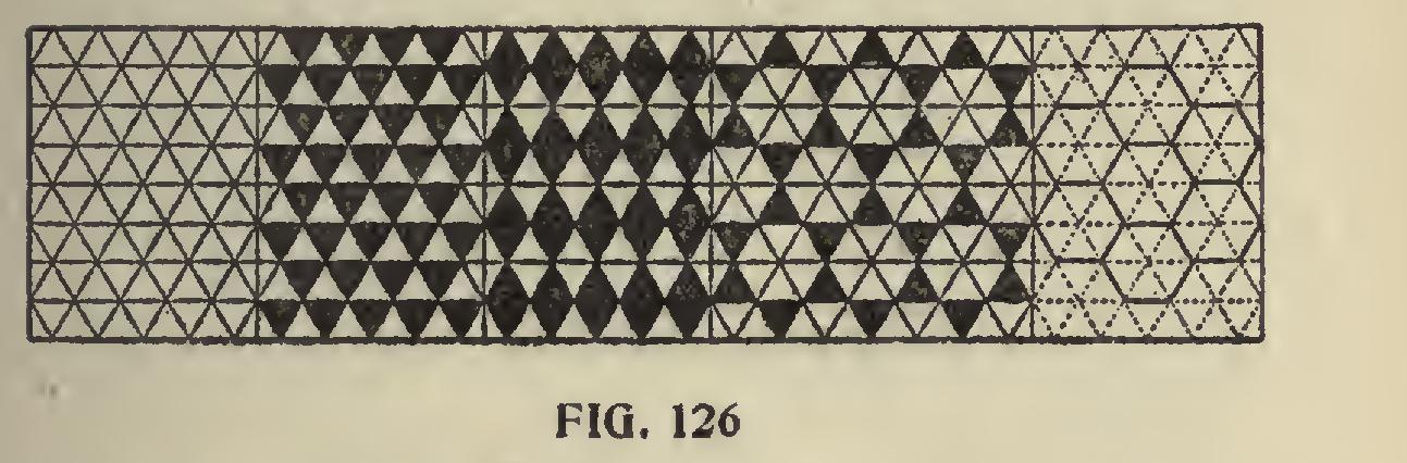
Arrangement of the Triangle.
The triangle can be arranged in many designs or patterns and leave no intervening spaces, as will be seen by referring to Fig. 126, which adapts itself to orna mental tile or inlaid work. Even the little honey bee understands the geometric principles in space saving and constructs her store house accordingly in hexagonal cells, which are in the form of six equilateral triangles and so arranged that they interlock each other as shown in part of the illustration. The equilateral triangle may indeed be classed as the monarch of all the polygons, for within its lines as a basis, any of the other polygons may be drawn to any desired size, as we will show later on under another head.