Possibilities of the Steel Square
circle, degrees, line, fig, shown, degree, squares, tongue, blade and pentagon
In Fig. 134 we show two squares with the blades and tongue intersecting at the figures that give the pentagon miter, and as will be seen, all of the angles form part of the pentagon. The stars are shown in connection with the same to further illustrate the accuracy of the illustration.
In Fig. 135 the lines are at 18 degrees on the square at the lower point of the star, and as will be seen, gives the miter for a frame star shape, the tongue giving the angle. From this it will be seen that the tongues of these squares are in a direct line with the center of the star. The squares at the top are set at 36 degrees, with their tongues in line with the 18 degree lines from the two lower squares, and form the angles for other parts of the star.

It will be seen that a star-shaped figure can be systematically framed either in the solid or in part, as shown, and that without first laying out a full-sized diagram, and the ten pieces will fit to their respective places. The figures 12 and 8 17-24 also furnish the basis for framing a root of this shape, and the general rule that applies to this, applies to all angles.

Tangents and Co=Tangents.
In Fig. 136 we have tried to make the subject of tangents and co-tangents clear by the use of two steel squares, placed as shown in connection with the quadrant. The blades and tongues intersecting at 12 and 12. Now, since a tangent is simply a straight line touching the side of a circle, we let the blades represent the straight lines intersecting a circle described from 12 on the tongue. Reading from the bottom up, the 36-degree line passes at 8.72 (8 17-24 inches) on the blade of square No. 1, and from this back to the heel is the tangent. Now, referring to square No. 2, what was 36 degrees on square No. 1 is 54 degrees, and passes at 16.51 (161 inches), and from this point back to the heel is the co-tangent. Both squares give iden tically the same cut, in other words, what the tongue gives in one, the blade gives in the other. If we read the degrees from the top to the right, we have the same thing, only reversed on the square.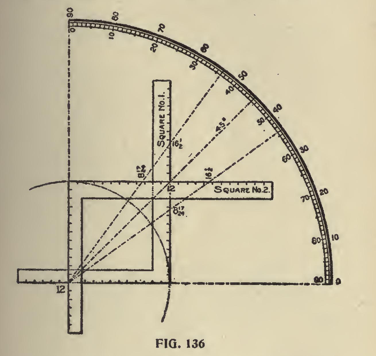
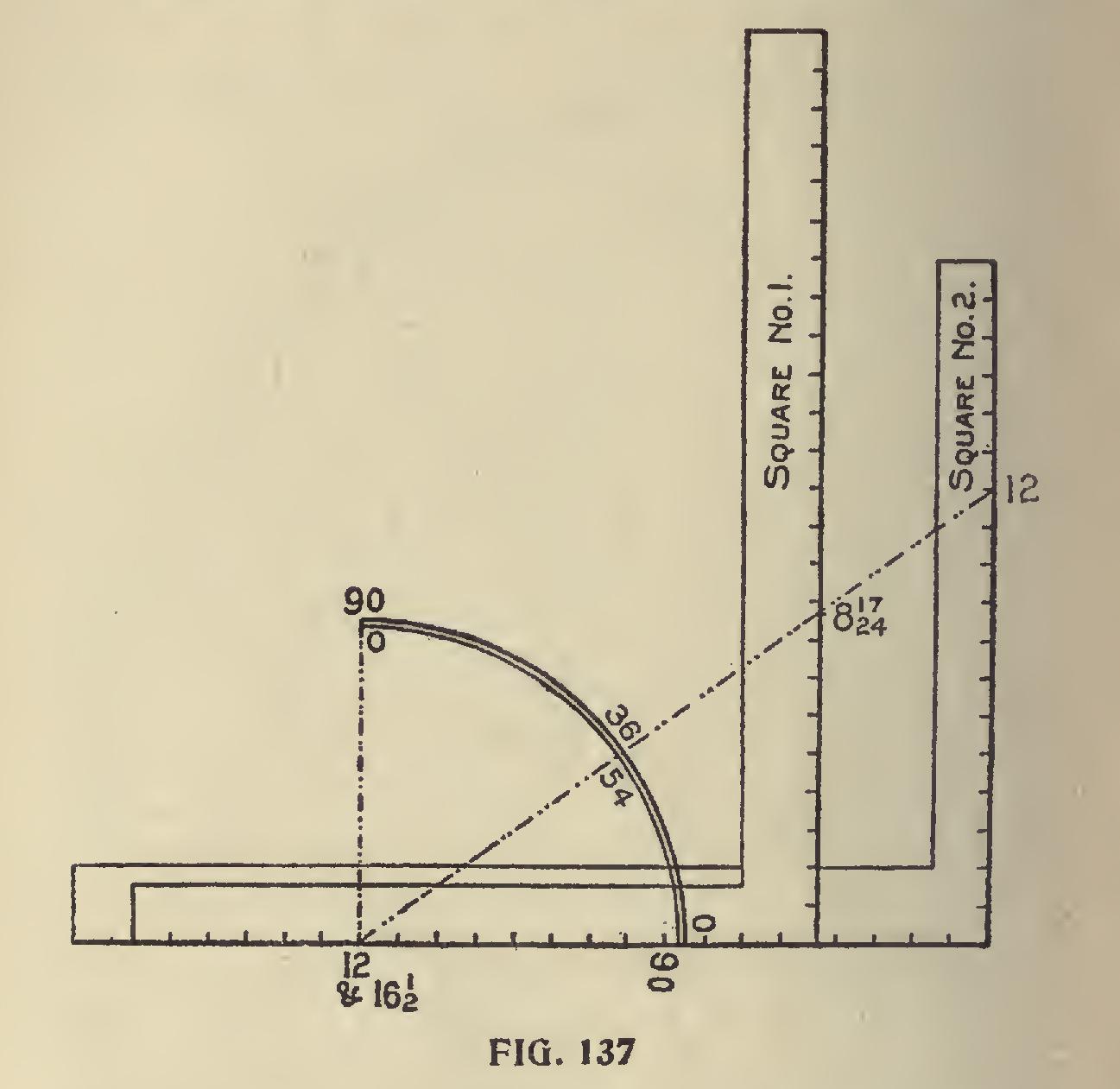
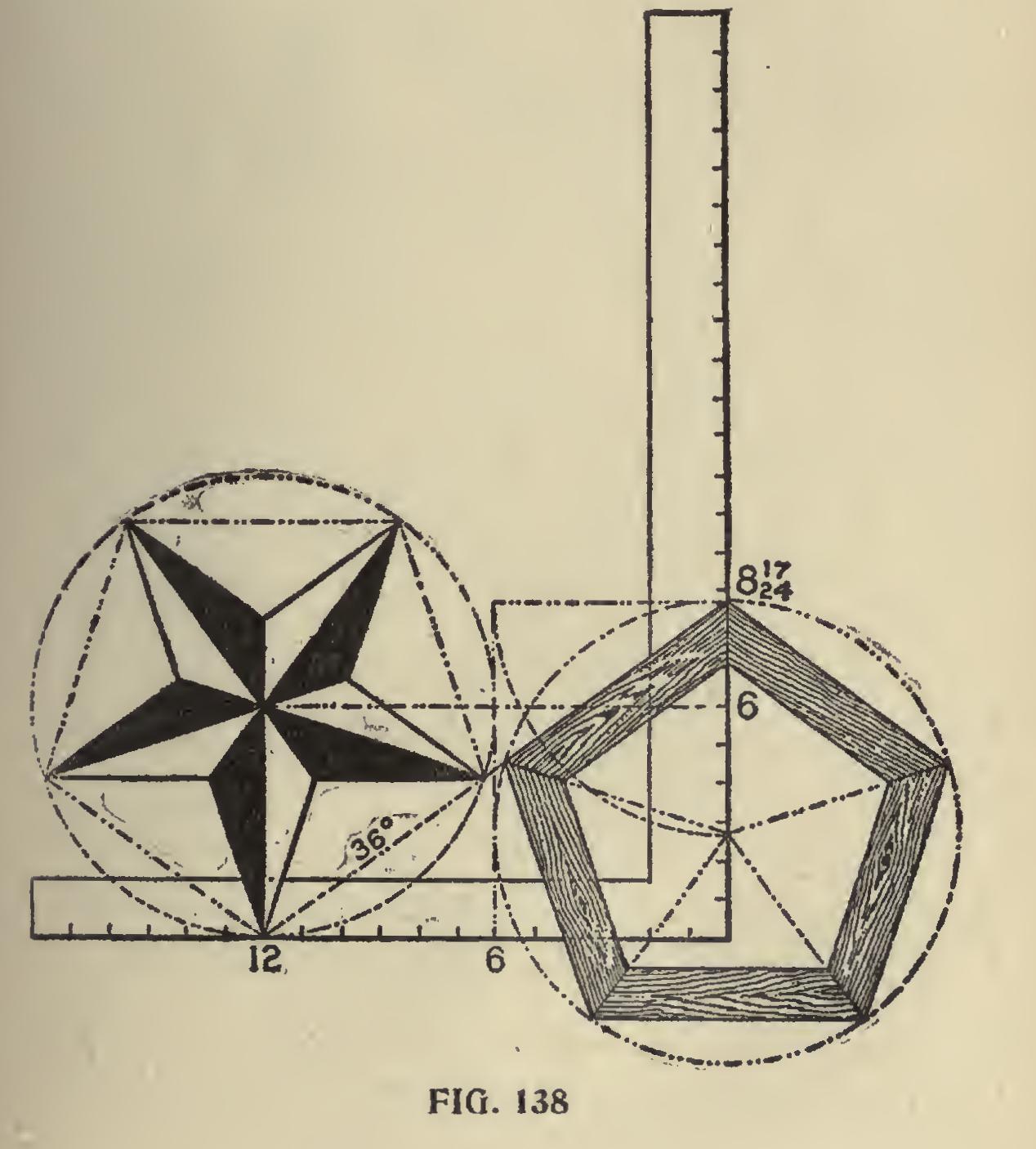
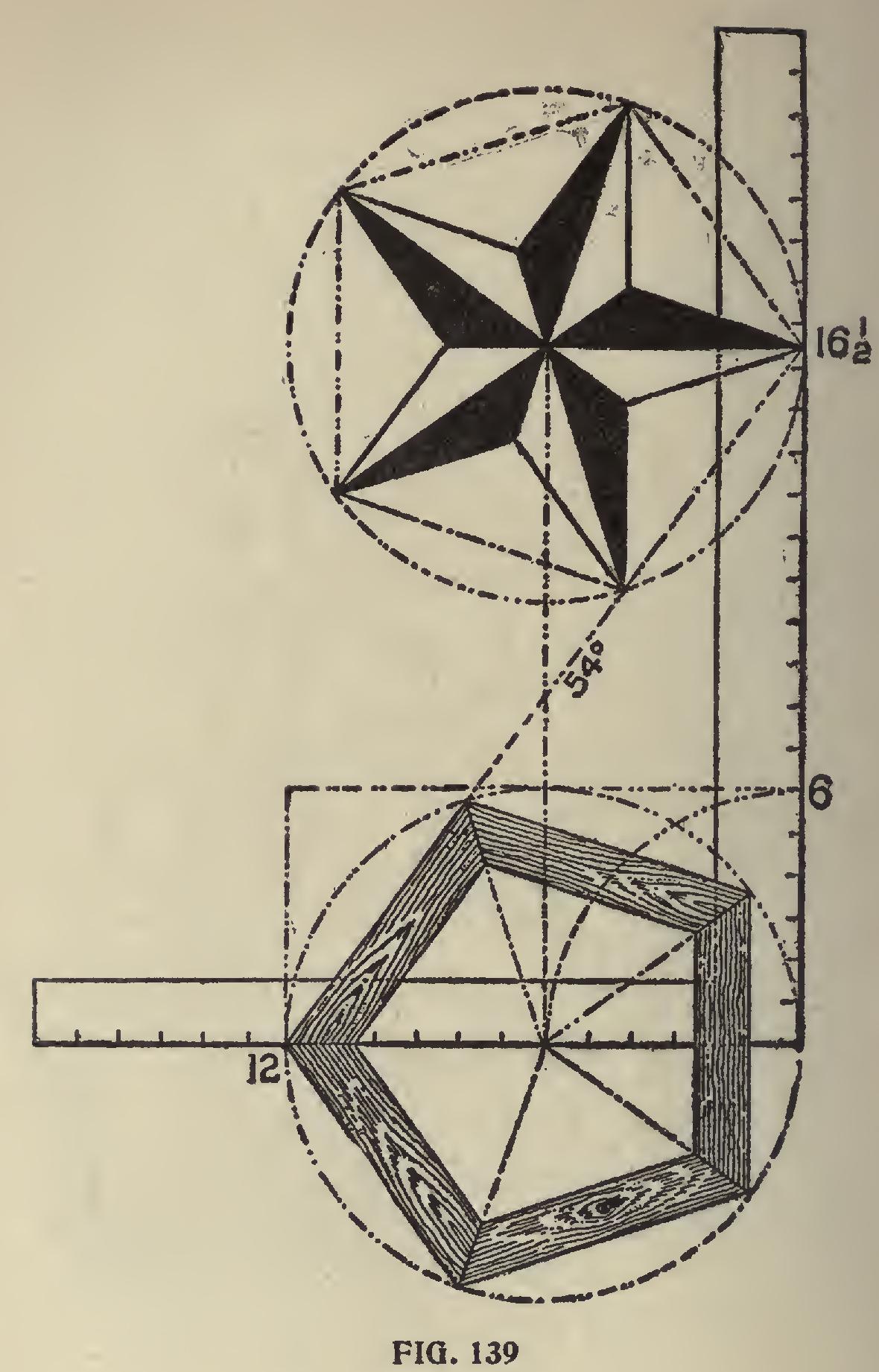
The 45-degree line, being at the half-way place on the square, remains unchanged. To illustrate this point a little further, we show two squares in a different position, as shown in Fig. 137, using the same figures on the squares as in Fig. 136 for the 36 and 54-degree line. Taking the squares separately, we show in Fig. 138, using the 36 degree line, the pentagon miter on the blade and the pentagon star resting at 12 on the tongue; while in Fig. 139, using the 54-degree line, the reverse is shown. In both of these illustrations the pentagon frame and star are inclosed in a circumscribed diameter of 12 inches, but they could be of any desired size.
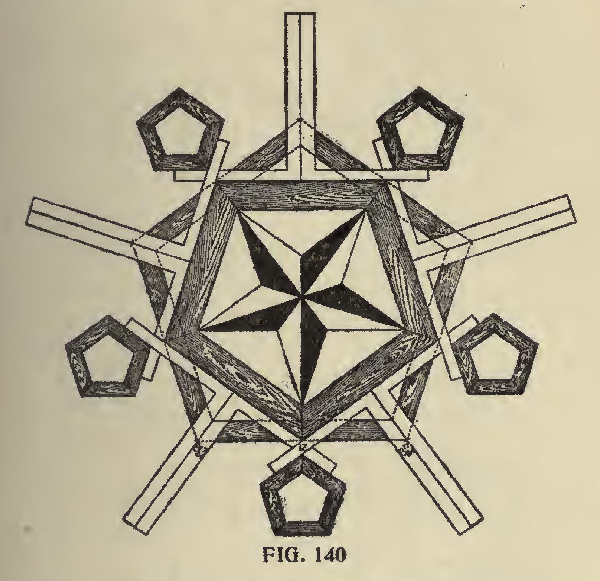
We have one more pentagonal illustration as shown in Fig. 140, we wish to present before passing on to some of the other polygons. We could go on and show other positions of the steel square in forming the pentagon and its miters, but the figures used on the steel square would conform to the figures here given or to their ratio. We will now call the reader's attention to some of the other polygonal figures, applying the same rule as for the pentagon or five-sided figure.
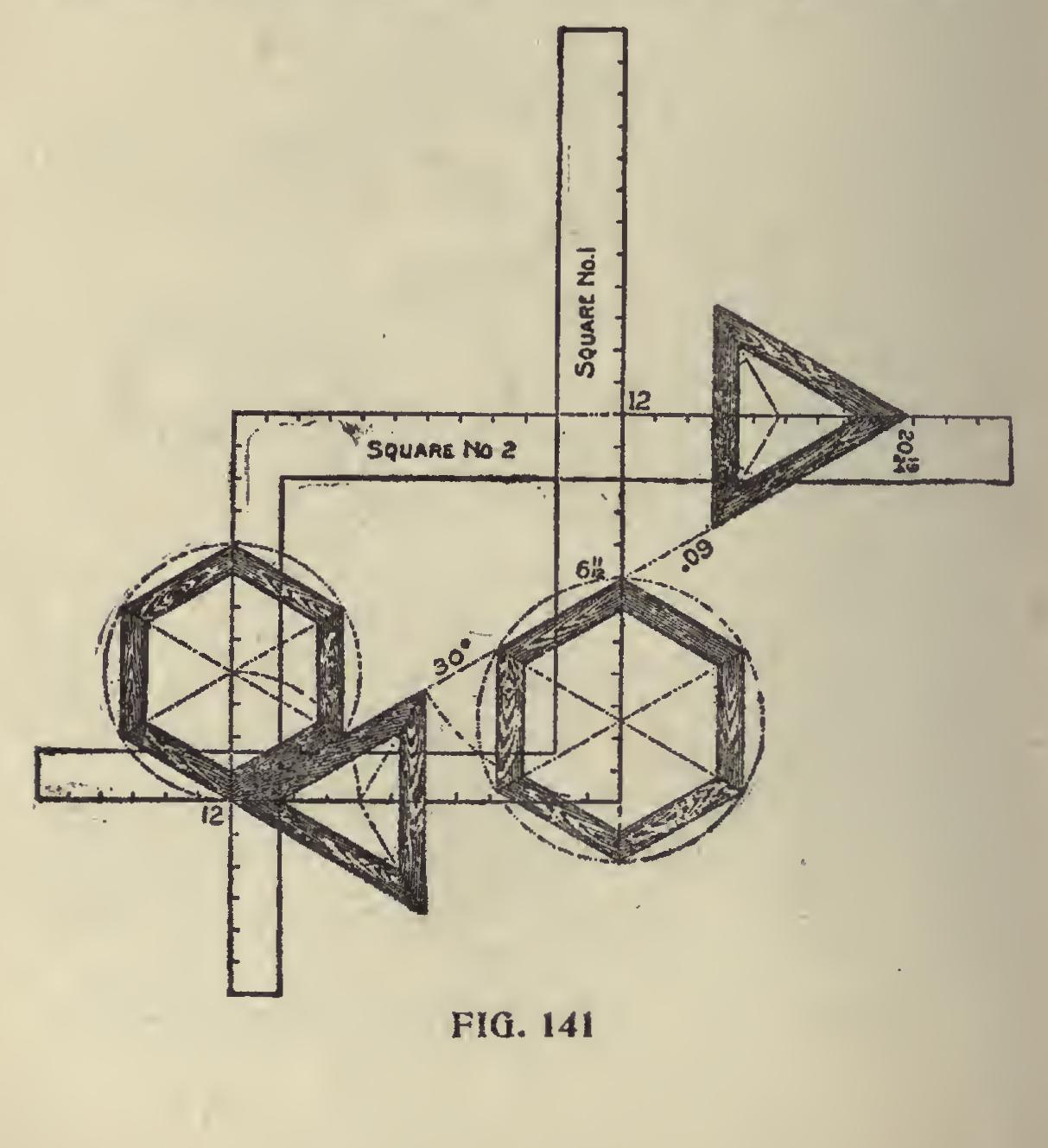
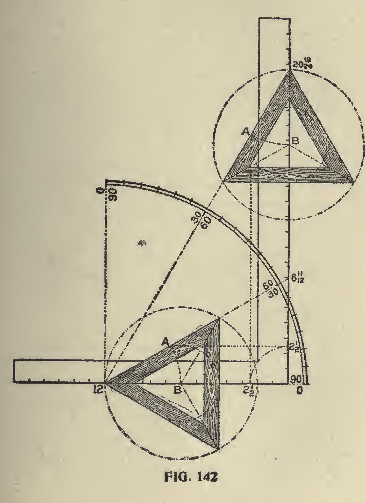
Degree Line of Triangle and Hexagon.—The triangle and hexagon are the only polygons whose miters can be had on the same degree line, which permits of using the same figures on the square as shown in Fig. 141. In this, we show two squares with but one degree line, which is 30 de grees on the square No. 1 and 60 degrees on square No. 2 and both giving the same cuts but reversed on the squares. Perhaps this point could be made more clear by using but one square as shown in Fig. 142. In this, the degree lines are shown for the 30 and 60 degrees and both giving the miter for the triangle. The tongue giving it in the former and the blade in the latter. In this ex ample, we show how to lay off a triangle of any inscribed diameter by setting off the radius, say 21 inches on the blade as shown, and squaring out to the degree line as at "A." Then with the length from 12 to "A," set off on the tongue will locate the center as at "B," or vice versa if the cut is wanted on the blade.
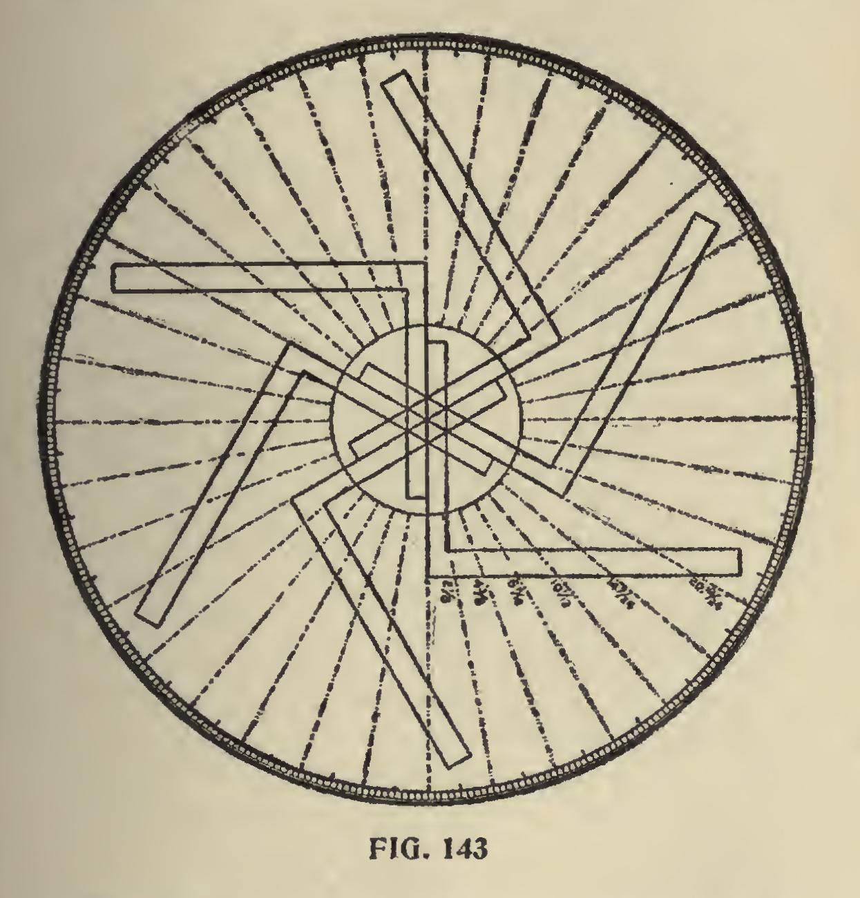
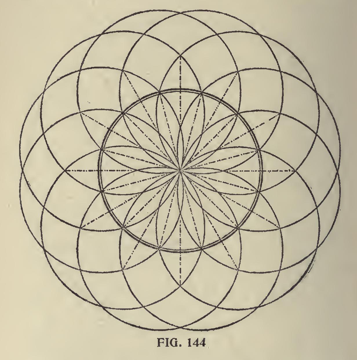
In Fig. 143, we show a circle with the degree divisions spaced on same with the aid of the steel square. We do not claim this to be the best way, nor would we use this method if we had a job of this kind to do, but it can be done and that very accur ately, by letting 12 on the tongue rest at the center and checking on the blade as follows: 2i, 41, 6 11-12, 10 1-12, 14 7-24 and 20 19-24 inches, which places the degree lines ten degrees apart. Then swing the square till the tongue rests in line over the last check and repeat the markings. Six movements of the square will complete the divisions and with a straight edge, which may be the blade of the square passing from the center and over the check marks, will divide the circle in divisions of ten degrees, and these may be divided with a compass into ten spaces, designating the degrees. Of course, the whole circle could have been divided with the compass by first dividing the circle into quarters or sixths and these spaces again into the required divisions, but the reader will understand that we are illustrating what may be done with the aid of the steel square. How ever, it will not be out of place to show what may be done with the compasses alone in laying off the degrees on the circle as shown in Fig. 144, and may be drawn as follows: Laying Off Degrees With Compasses.—With the compass describe the degree circle and without changing the radius, set the needle point at any place on the circle, describe another circle and at the intersection with the first circle, describe another circle and continue until all of the inter sections have been used; then with a straight edge lay off the lines through the center to the intersection of the points of the outer circles. It will be seen that the degree circle has been divided into twenty-four equal divisions or 15 degrees apart. These divisions could be again divided in like manner down to 5 degrees by set ting the needle point at one-third of the space on the circle and thereafter on the intersections as described above.