Possibilities of the Steel Square
shown, blade, figure, contained, figures, fig, lines and line
In Fig. 127, is shown a hexagonal figure in general design and all of the miters can be had on 12 and 6 11-12 as indicated on the square. The blade giving the hexagonal and the tongue the triangular cuts. This proportion, of course, the reader will understand, taken at any other part on the blade and tongue would give the same result, as every fractional part of the divisions on the blade represents a scale, but we will not take the time now to explain. The same cuts exist again at 12 on the tongue and 20 19-24 on the blade, but the cuts on the square are just the reverse.

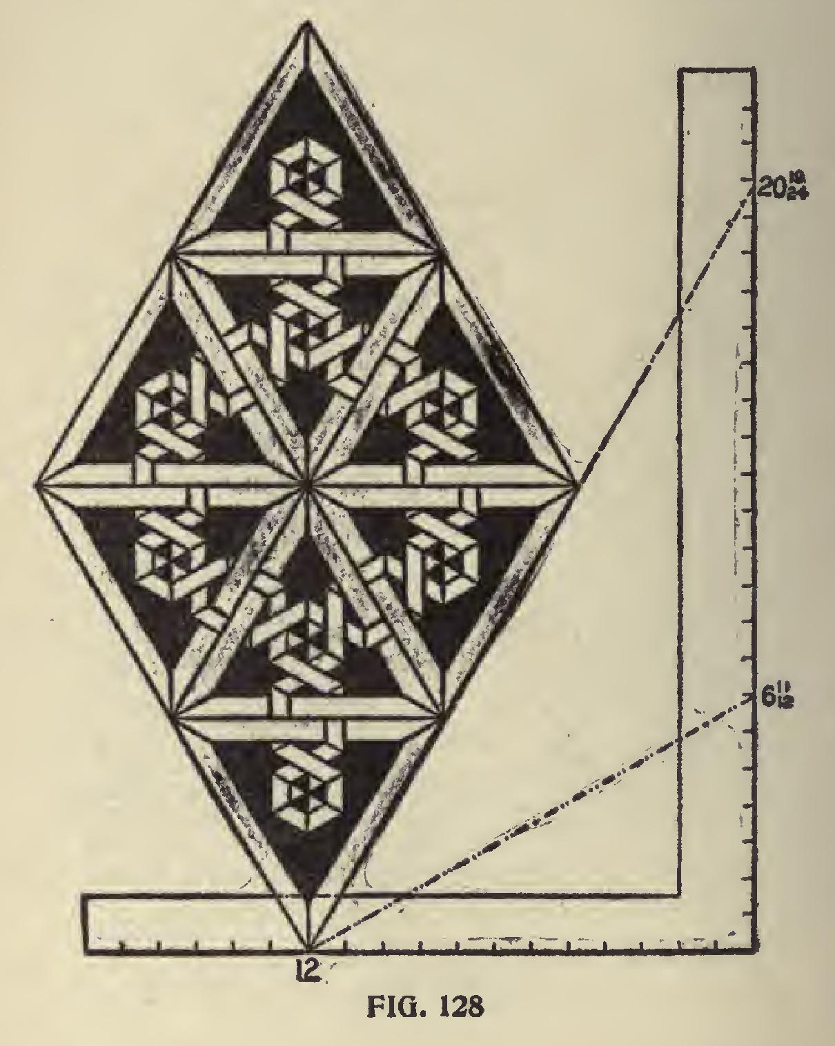
In Fig. 128 is shown another design and is worked on the same degree lines as in the previous figure; what we said of that figure is just as appli cable to this figure. Either of these designs furnish good examples for inlaid work and with , care in selection of color of wood would make a very attractive piece of work.
Application of Degrees.
Too much cannot be said as to the possibilities that come in range of the common steel square in connection with the degrees contained in the eighth part of a circle as applied to the right-angle triangle and their tangents. For they cover the whole field of miters whether on a level or incline plane. The illustrations that we have been giving pertain to the miters resting at a level plane, but they form the basis for miters resting at an inclined plane, which pertain to the side cuts of rafters for any shaped building, the working out of geometrical hand railing, etc.
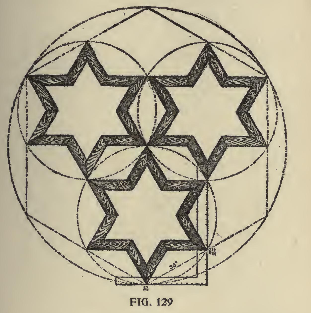
In Fig. 129 are shown three hexagonal star
shaped frames inclosed in circles and these are contained in one large hexagon and the whole in one large circle.
The reader will notice that the figures given on the square are the same as those given in pre vious illustrations for the miter of the hexagon.
The blade will give the angle for the inner points, while the tongue will give it for the outer points, or if 60 degrees is used, which falls at 20 19-24 on the blade, then the angles will be just the reverse on the square.
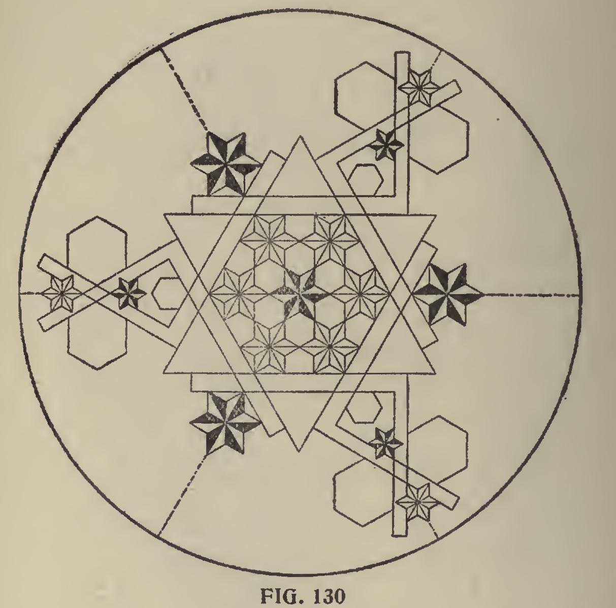
In Fig. 130 are shown six squares laid in pairs with their blades and tongues intersecting each other at the figures that give the hexagon miter, and produces one of the most beautiful examples in miter work. All of the angles about the squares form some part of the hexagon and it will be seen that the large circle that incloses the figure is equally divided into six parts.
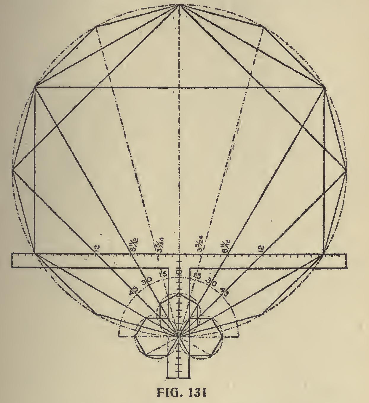
In Fig. 131 is shown another form of drawing polygonal figures. In this we show two squares,
though only one is needed. The second one is given for effect in balancing the drawing, as it will be seen that the same figures are used on both squares. The degree lines leave the 12 on the tongues at 15 degrees apart and intersect the figures on the blade as shown. Now since 15 is a multiple of the number of degrees that form several of the polygons, they are contained in this figure, as 15 is contained in 180 twelve times, 30 is contained six times, 45 is contained four times and 60 is contained three times. By re ferring to the illustration the reader will see that polygons of the above number of sides are all contained in this figure.
In Fig. 132 we have carried the above a little further, showing the same polygons as in the pre ceding figure, but in this case they have blossomed out into a flower.
In Fig. 133 is shown a diagram whereby the angles and dimensions for any of the polygons may be accurately drawn by a system of lines passing through .12 on the tongue of the square.
For illustration we have taken the heptagon or seven-sided figure.
The semi-circle 7-A is first drawn, which may be to any desired size. Place the steel square as shown with the 12-inch mark at the center.
Then draw a line from 12, passing at 5 19-24 on the blade (which are the figures to use for the miter), and continue on, intersecting the semi circle at 1. Then A-1 will represent one-seventh of the semi-circle and is equal to the spacing set off at 1, 2, 3, etc. Draw lines from these points to the center at 12, as shown.
Drawing a Heptagon.
Now, suppose we wish to draw a heptagon with a twelve-inch inscribed diameter. Set off 5 19-24 on the line 12-1, as at B, and bisect the line 12-B as shown, and where the bisecting line intersects the perpendicular line from 12, as at C, will be the center from which to strike the required radius.
By indefinitely extending the lines 1, 2, 3, etc., below 12, as shown, heptagons with any desired circumscribed radius may be readily determined by simply setting off the radius on the perpendic ular line as shown, and where the circle cuts the extended lines determines the length of their chords or sides. In the illustration we have shown three sizes. Proceed in like manner for any of the other polygons, but using the figures on the blade of the square that give their miters.