Right Jack Fig21
rafter, length, run, pitch, square, hip, feet and fig
Hip Rafters.—Fig. 24, represents the plan of a roof as furnished by an architect. Fig. 25 shows the square set to the pitch of the common rafter, while Fig. 26 shows the same for the hip rafter. The squares as set give plumb and level cuts. Fig. 24 is the rafter plan of the house 18 by 24 feet; the rafters are laid off on the level, and measure nine feet from center of ridge to outside of wall; there should be a rafter pattern with a plumb cut at one end, and a foot cut at the other, gotten out as previously shown. (Fig. 25, 26).

When the rafter foot is marked, place 12 on the long blade of the square to the wall line, as in Fig. 25, and mark across the rafter at the outside of the short blade, and slide the square up the rafter and place the 12 of the long blade to the mark last made and mark outside the short blade as before, repeat the application until nine feet are measured off, and then the length of the rafter is correct; remember to mark off one-half the thickness of ridge-piece, which is done by measur ing at right-angles back from the plumb cut. The rafters are laid off on part of plan to show the appearance of the rafters in a roof of this kind, but for working purposes the rafters 1, 2, 3, 4, 5, and 6, with one hip rafter, are all that are required.
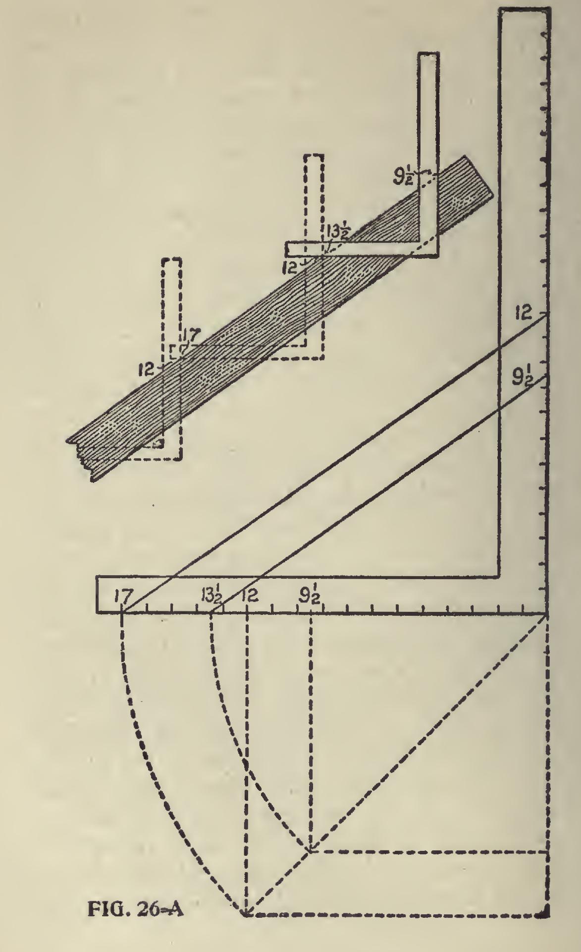
Length of Hip Rafters—How to Get the Inches and Fractions.—Fig. 26A shows how to get the length of a hip rafter for a half pitch roof for a building 17 feet 7 inches wide, making 8 feet 9i inches in the run. For the 8 feet in the run 17 and 12 are taken eight times on the square. The reason 17 is used is because it is the practical length of the diagonal of a one-foot square, and 12 is used because it represents the half pitch to a one foot run, as shown in Fig. 26A. Therefore these figures taken on the steel square eight times will give the length for the eight feet in the run, and for the nine and one-half inches proceed in the same way taking the diagonal of nine and one half inches, which is thirteen and one-half, and a line drawn from 13i parallel with the one from 17 to 12, and the point of intersection on the blade will be the figures to use for the last application of the steel square to obtain the length for do extra nine and one-half inches in the run. In the case of the half pitch, the rise being equal to the run, the figures on the blade are the same as those in the run. This should not be allowed to confuse, as it does not occur in any other pitch.
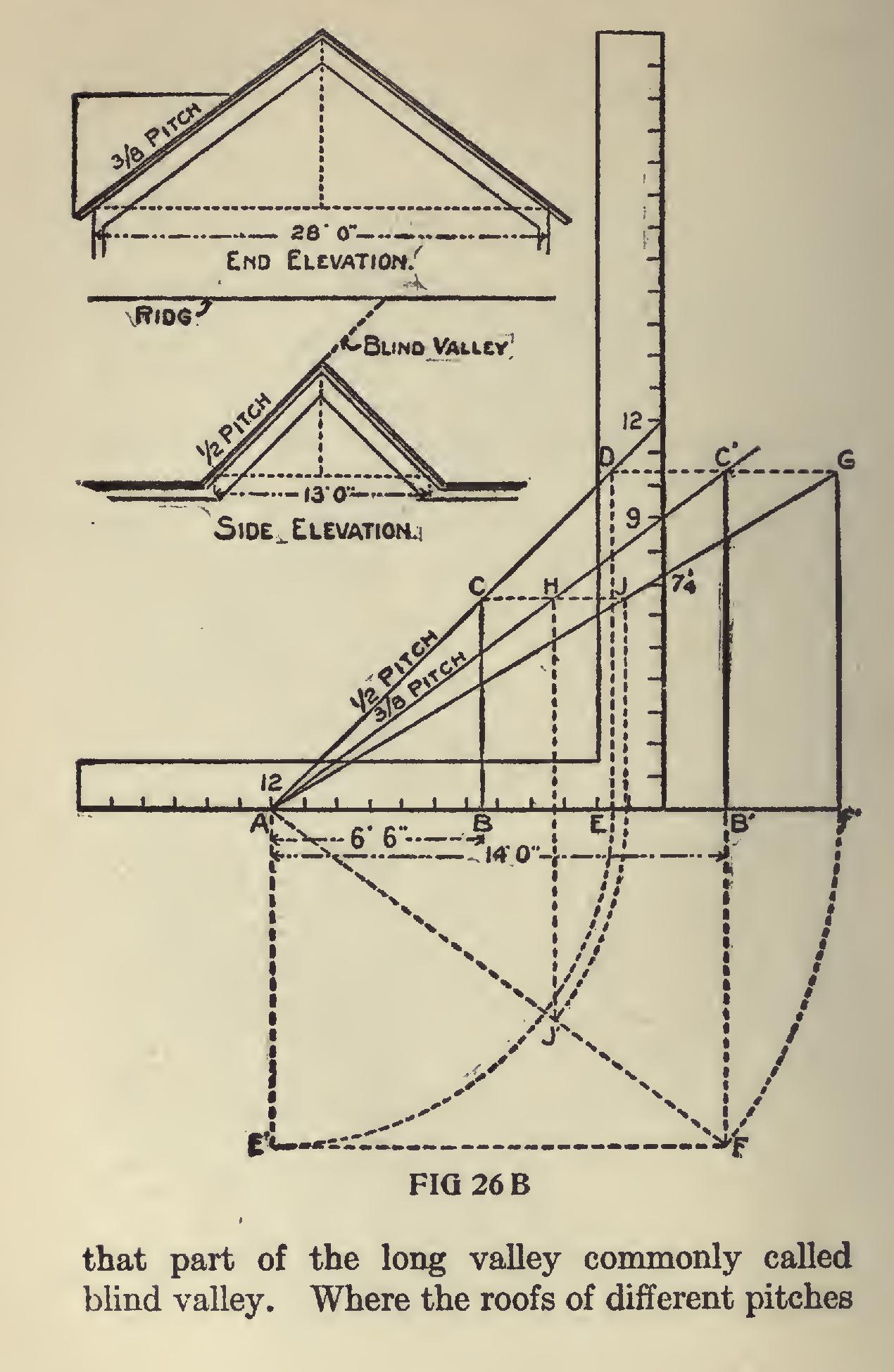
Valley Rafter for Gable.—To get the length of a valley rafter for a gable of half pitch to fit over another of three-eighths pitch, first lay off the pitches 12 to 12 and 12 to 9, as shown in Fig. 26B.
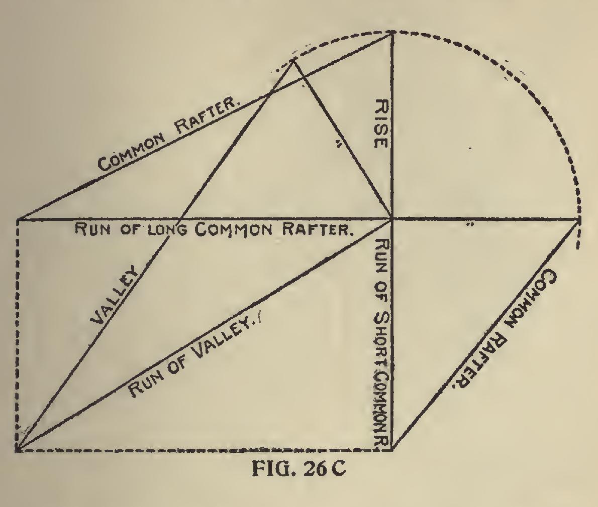
Now assuming that the run for the half pitch is six feet six inches and that for the three-eighths pitch is fourteen feet, we lay off these lengths on the run as shown at A B and A B'. Square up from B and B' to the respective pitches inter secting at C and C'. Then A C will be the length per one inch scale for the common rafter for the half pitch, and A C' will be the same for the three eighths pitch. Now for the length of the valley, square over from C' to D and drop to E on the run, and this transferred to A E' represents the end, and A B' the side of a plan whose diagonal A F will represent the run for the long valley to catch the ridge of the main gable, and this trans ferred to F' and erect the rise F' G, and draw the line A G which will be the length of the long valley, and by squaring over from B C intersect ing A G at J. Thus A J will be the length for the short valley and its run will be A J. The point at H is at the intersection of the ridge of the half pitch with the main roof. J G represents are of the same height it is quite an easy matter to arrive at the length of the valley, as their runs form the sides of the plan as shown in Fig. 26C, which needs no further explanation.
Curved Hip Rafters.—Fig. 27 shows how a curved hip-rafter may be obtained. The rafter shown in this instance is ogee in shape, but it makes no difference what shape the common rafter may be, the proper shape and length of hip may be obtained by this method. It will be noticed that one side of the example shown is wider than the other; this is to show that the rule will work correctly where the sides are une qual in width, as well as where they are equal.
represent the plan of the roof. F C G the profile of the wide side of the rafter. First, divide this rafter G C into any number of parts — in this case eight. Transfer these points to the miter line E B, or, what is the same, the line in the plan representing the hip rafter. From the points thus estab lished in E B, erect perpendiculars indefinitely. With the dividers take the distance from the points in the line F C, measuring to the points in the profile G C, and set the same off on corresponding lines, measuring from E B, thus establishing the points 1, 2, 3, etc. ; then a line traced through these points will be the required hip rafter.