Right Jack Fig21
rafter, line, cuts, valley, run, hip and common
Common Rafters.
For the common rafter on the narrow side, continue the lines from E B parallel with the lines of the plan H E and A B. Draw A D at right angles to these lines. With the dividers as before, measuring from F C to the points in G C, set off corresponding distances from A D, thus establishing the points shown between A and H. A line traced through the points thus obtained will be the line of the rafter on the narrow side. This is supposed to be the return roof of a veranda, but is only shown as an example, for it is not customary to build verandas nowadays with an ogee roof, but with a rafter having a de pression or cove in it. For accuracy it would be as well to make nearly twice the number of divis ions shown from 1 to 8, as are there represented.
In speaking further of roof-framing and par ticularly of framing of hip and valley roofs, Mr. Woods says: Much has been said and can be said on the subject, but it is my aim to say as little and do as much as I can to make the sub ject clear. Every carpenter knows that the run and rise of the rafter taken on the square will give the seat and plumb cuts, but inasmuch as buildings are not all of the same width, it requires a different set of figures for each run, and as it requires an extra calculation to find the run of the hip or valley, it is better to use the full scale for a one-foot run of the common rafter, which answers for any run.
To Find the Length and Cut of Rafters.—Re ferring to Fig. 28, we show a square bounded by from B. B-A represents the run of the common rafter. E-A represents the run of the octagon hip or valley, and C-A the same for the common hip or valley, their lengths being 12, 13, and 17 respectively. Now since 12, 13, and 17 are fixed numbers, we take them on the tongue of the square, as shown in Fig. 29. Now suppose we want to find the lengths and cuts of the rafters for the i pitch. We take 9 on the blade. Why? Because the run being 12 inches, the span must be two times 12, which equals 24, and since the pitch is reckoned by the span, we find that 1 of 24 is 9, which represents the rise to the foot run.

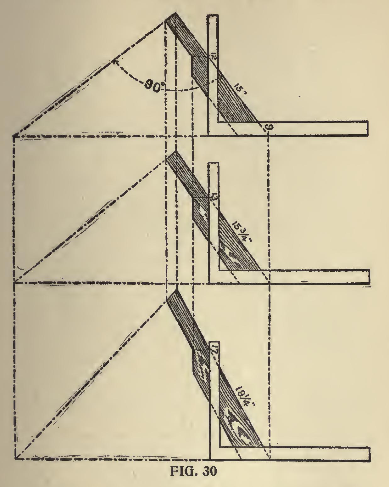
Then 12 and 9 give the seat and plumb cuts for the common rafter, 13 and 9 for the octagon hip or valley, and 17 and 9 give the same for the common hip or valley. In Fig. 30 we show each separately.
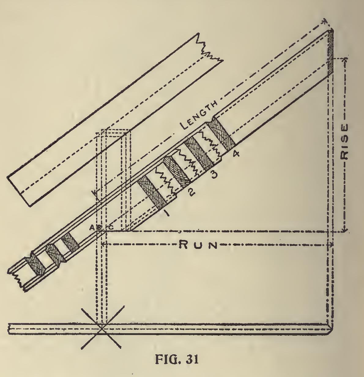
The Measurement Line of Hips and Valleys is a line along the center of its back, and just where to place the square on the side of the rafter so as to make the cuts and length come right at that point is a question that taxes the skill of most carpenters, especially so when the rafters are so backed. In Fig. 31, we have tried to make
the above points clear.
First, we show the plan of the rafter. The cross lines on same represent an external corner for the 1:*p and valley respectively. Above the plan is shown the elevation. The sections 1, 2, 3, 4, represent the position of the rafters under the following conditions : No. 1 hip when not backed, No. 2 hip when backed, No. 3 valley when not backed, No. 4 valley when backed. By tracing the bottom line of each section down to the line C-A which is parallel to the seat cut and is regulated by the height given the upper edge of the common rafter above the corner of the plate as at A-B, will show how deep the notch ing should be for each rafter. No. 1 cuts into the right hand vertical line from the plan, which would make it stand at the right height above the plate, but in order to make the seat cut clear the corner of plate, it is necessary to cut into the center line above the plan. No. 2 cuts into the same points as No. 1, but owing to its being backed, the seat cut drops accordingly. No. 3 cuts into the center vertical line, and in order to clear the edges of the plate must cut out at the sides to the left vertical line. No. 4 cuts in the same as the latter, but as much lower than No. 3 as No. 2 is below No. 1.
The outer vertical lines from the plan rep resent the width of the rafter. Therefore if the rafter be two inches thick, would be one inch apart, and this amount set off along the seat line (or a line parallel with it) will give the gauge point on the side of the rafter. To make this clearer refer to Fig. 30; 17 and 9 gives the cuts. Now leaving the square rest as it is, measure back from 17 one-half the thickness of the rafter. and this will be the gauge line point from which to remove the wood back to the center line of hip, and the measurement from the edge of the rafter taken vertically down to the gauge point set off on the plumb cut regulates how far apart the parallel lines of the seat cuts will be under the above conditions. This rule applies to any roof so long as the pitches are regular.