80 Heating and Ventilation
water, pressure, system, tank, expansion, pipe, heat and generator
Pressure Systems of Hot-Water Heating. Heating by means of a forced circulation of hot water is not in general use in America. When adopted, it is principally in connection with large buildings, and in such installations many meth ods are employed. In numerous instances, hot water installations have been under a pressure of from ten to fifteen pounds by the application of a safety-valve on the expansion tank, set to operate at this desired pressure. There is, how ever, an element of danger in this practice, for if the mechanism of the safety-valve should stick or for any reason fail to operate, an explosion of more or less disastrous consequences would in all probability result. Because of the risk involved, this practice, fortunately, has now been largely discontinued, especially since sev eral mercurial devices have been placed on the market which permit of the system carrying a pressure of eight or ten pounds without incur ring any danger whatever.
On large installations where high-pressure steam boilers are used for manufacturing or mechanical purposes, certain systems of heat ing by a forced circulation of hot water can be adopted with good success. The principle in volved requires a pumping of the return water through one or more heaters in which exhaust or live steam is employed for heating, the hot water being forced through the heating system by the pump, which may be of either the rotary or centrifugal type. Where plenty of exhaust steam can be obtained for the purpose, there is little or no expense in connection with this style of heating. The available heat units in the ex haust, after heating all necessary feed-water for the boiler, represent probably 80 per cent of its original value; in other words, with an allow ance of 5 per cent for the requirements of the engine, and 15 per cent for the feed-water heater, there is left available for heating pur poses probably 80 per cent of the heat units in the steam generated at the boiler. Where this proportion is not sufficient, live steam at a re duced pressure may be mixed with the exhaust in order to provide power to meet the require ments of the work. The pump receives the cooler return water, and forces it through the heater at a velocity of from 250 to 300 feet per minute, and at a temperature of about 200°.
Accelerated Systems of Hot-Water Heating. Systems of hot-water heating involving the use of special devices for accelerating the circula tion of the hot water, have in recent years come into rapidly increasing popularity. The older of these special appliances for accelerating cir culation are the Phelps Heat-Retainer, the Honeywell Generator, and the Pierce Heat Economizer.

The Phelps Heat Retainer, illustrated in Fig. 60, consists of a double-acting valve enclosed within an iron box which is placed on the ex pansion pipe between the tank and the heating system. The valve disc, opening toward the expansion tank, is weighted, the weight being so adjusted that when the pressure on the sys tem reaches about 161/2 pounds it is lifted, caus ing the valve to operate, which, in its action, re lieves the pressure, al lowing the increased bulk of the water to en ter the expansion tank.
The opposite end of the valve opens toward the heating system; and as this is not equipped with a weight, the water in the tank flows down into the heating system unchecked as soon as the pressure on the valve is removed, this action keeping the system full of water and free from the formation of a vac uum. The pressure of pounds represents a temperature in the water of about 250 de grees.
The Honeywell gen erator and the Pierce heat - economizer a r e mercury appliances somewhat similar to each other in construction and operation. Fig. 61 is a cross-section of a Honeywell generator. At the top is the elliptical-shaped casting A, which is connected to the bottle-shaped casting B by the pipe C. This pipe extends almost to the bottom of the generator, terminat ing in the cup-shaped shoe D. A smaller pipe E, curved at the bottom to fit into an orifice in the side of the shoe D, passes up through the center of the pipe C, the two pipes being of equal height at the top. The plug F screws into the bottom of the casting B, making it entirely tight, except for the side opening G, into which the expansion line from the heating system is connected. There is also a small opening at H which is sealed. The plug here can be removed, and the generator drained of all water, without disturbing the mercury which fills the bottom of the casting B to the depth of about inches. The dash line shows the height of mercury when the water is cold and there is no fire in the heater.
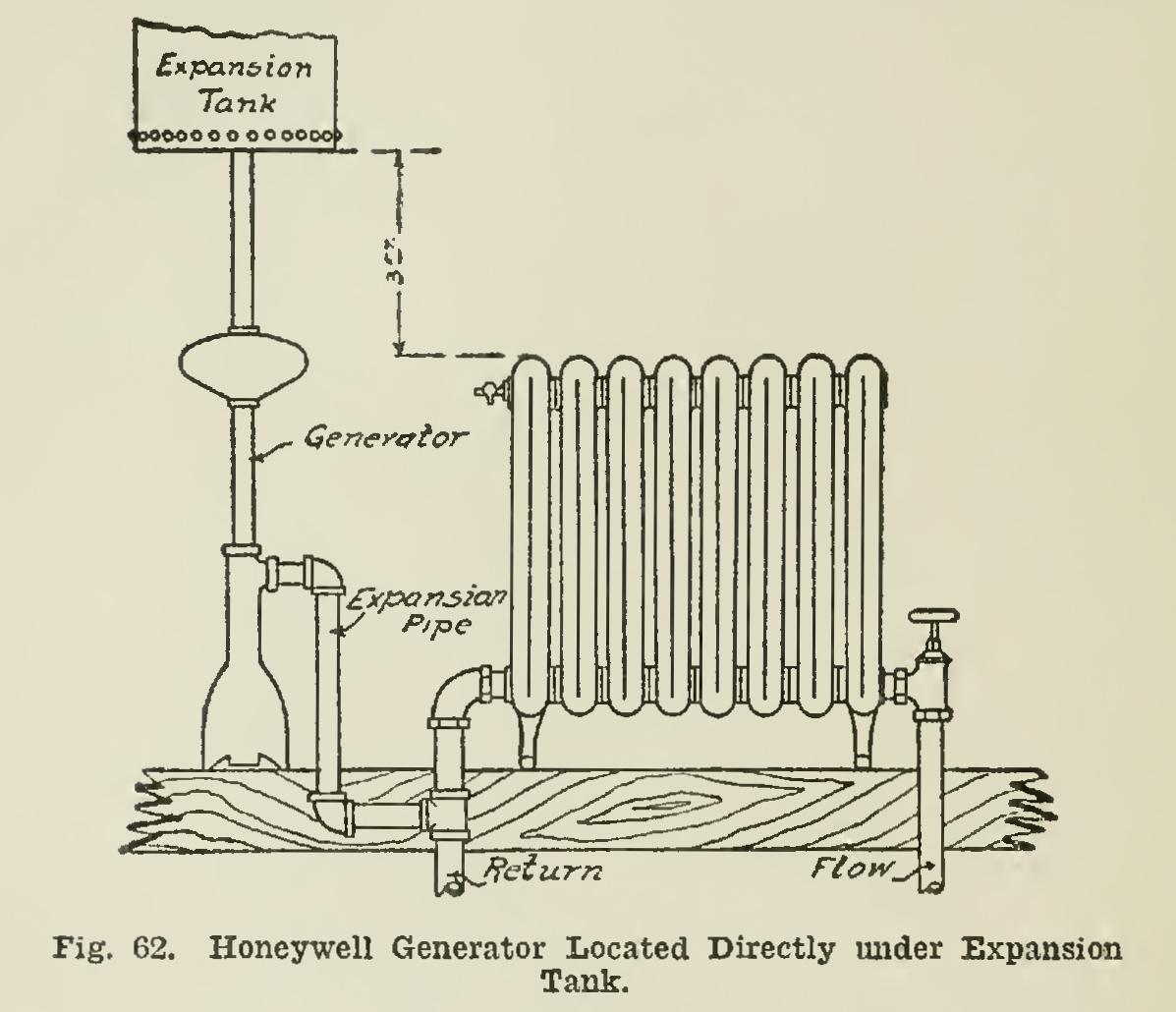
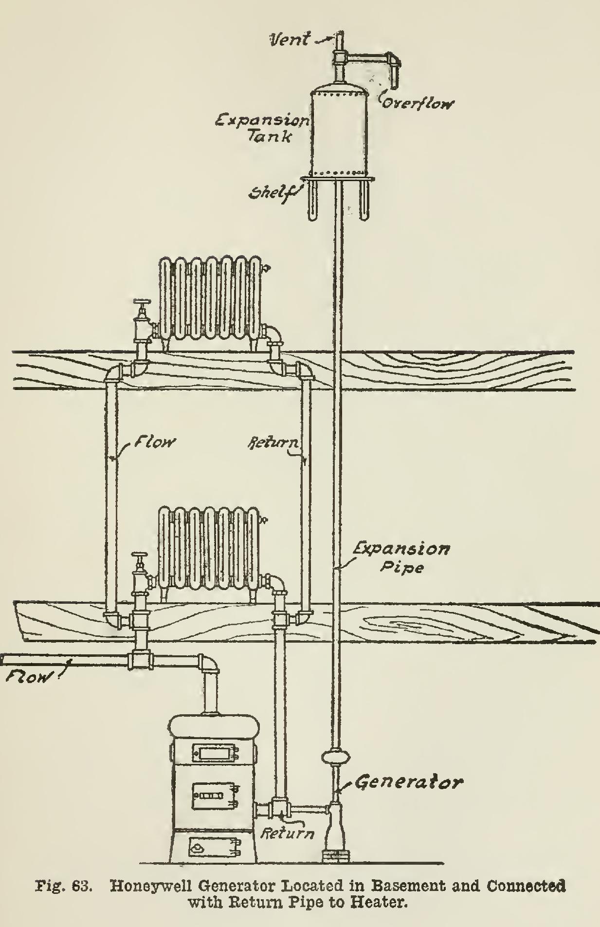
The generator may be located directly under the expansion tank, as illustrated in Fig. 62, or it may be placed in the basement near the rear of the heater, and from here connected with the return pipe, as shown in Fig. 63. Of the two, this latter position is the one preferred. In the event of such location, the expansion pipe is connected from the top of the generator, whence it rises to the ceiling of the basement, and is car ried along until a point is reached where it is convenient to rise to the expansion tank.