80 Heating and Ventilation
water, pipe, top, mercury, system, generator, cent and accelerated
The operation of the generator on a heating system can be described as follows: Almost as soon as the fire is started, the water in the sys tem begins to expand, the expansion through the opening G (Fig. 61) pressing down on the mercury in the bottom of the generator. As the power of the expansion continues to increase, the supply of mercury is forced up the stand pipe C and the small circulating pipe E. The mercury in the bottom of the generator is low ered to the top side of the inlet in the shoe of the circulating pipe E. At this point the mer cury will have reached the top of both the outer standpipe and the circulating tube; and the water, having forced it below the opening of the circulating pipe E, will itself enter and pass through this pipe, carrying a quantity of mercury with it.
When the water and mercury reach the top of this pipe, the water will pass around the dia phragm or deflector in the top of the casting A, and out through the expansion tank; while the mercury, owing to its density being far greater than that of the water, will separate itself at the top of pipe E, and return to the bottom of the generator through pipe C, maintaining a constant circu lation through the generator, in this manner acting quite similarly to a balanced valve.
The amount of mercury in the generator is sufficient to hold the pressure to about 10 pounds, or to a temperature of 240° F., without permitting a boiling of the water in the system. The deflector or baffle-plate in the top of casting A prevents loss of mercury when the apparatus is filled from city pressure, or in case a boiling of the water arises in the system.
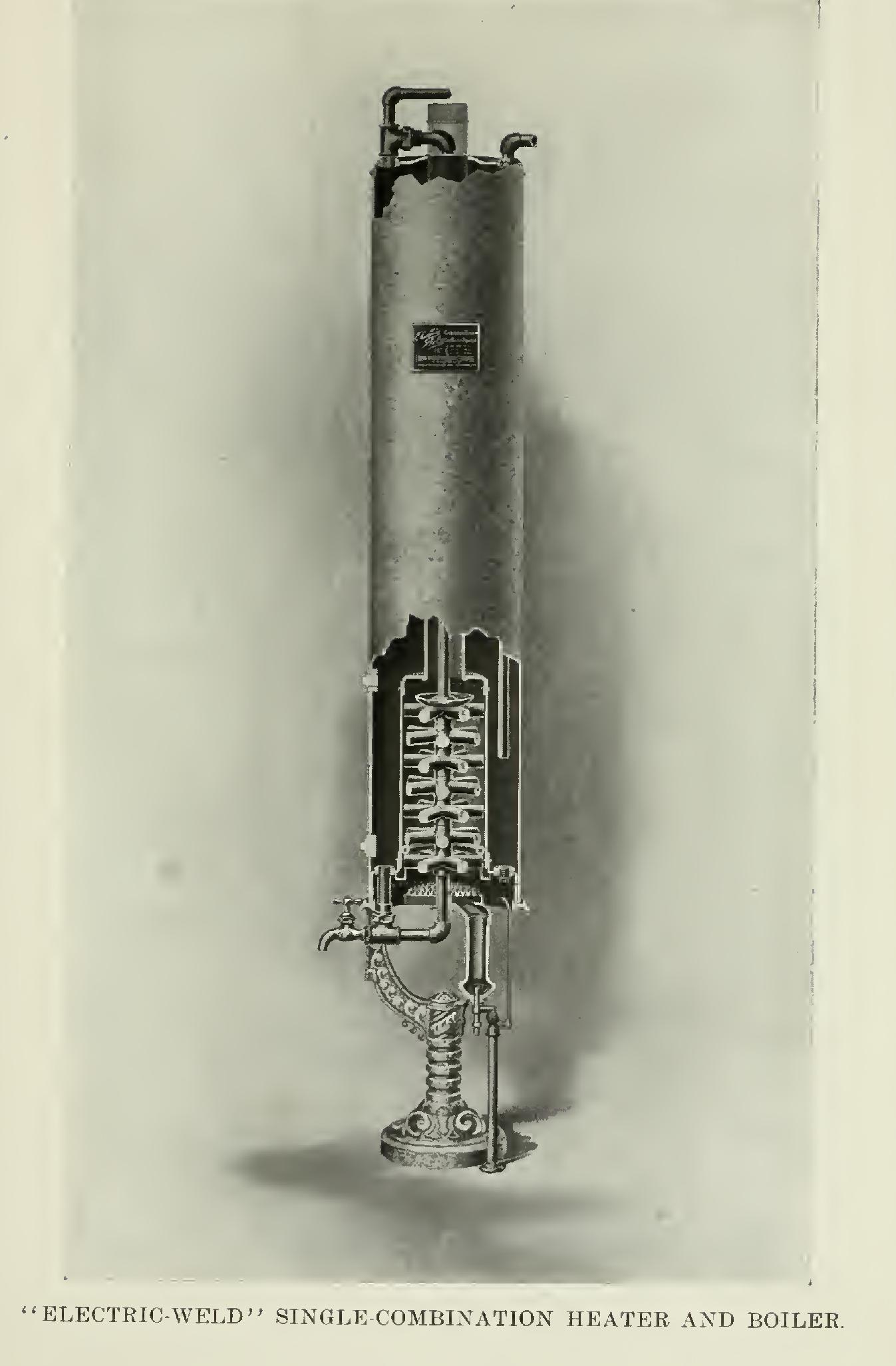
The Pierce heat-economizer, Fig. 64, is not unlike the Honeywell generator. The principle involved in its construction—two pipes, one within the other, the outer pipe connecting the top casting (which is provided with deflectors cast on the inside), with the lower casting hold ing the mercury—is qUite the same as that found in the similar appliance already described.
Many are the advantages derived from the use of any one of these appliances. Owing to the increase in the range of temperature it affords (up to the amount of radiating surface required should be about ten per cent less than that needed in the regular gravity sys tem, and, where other surrounding conditions are favorable, it may be reduced fifteen or twenty per cent.
The increased pressure generated more than doubles the velocity of the circulation. Its usage permits of smaller-sized supply and return pipes and of reduced radiator tappings, consequently allowing of the use of smaller valves and fittings, and substantially reducing the cost of materials as well as the labor of installation.
The attachment of an accelerating appliance eliminates practically fifteen per cent of the water from the system, causing it to respond more quickly; and moreover, its use saves a pro portionately large amount of fuel. A large pro portion of hot-water work to-day is erected according to such plans.
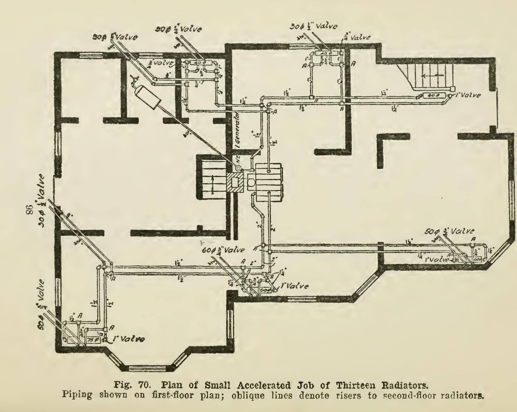
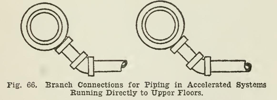
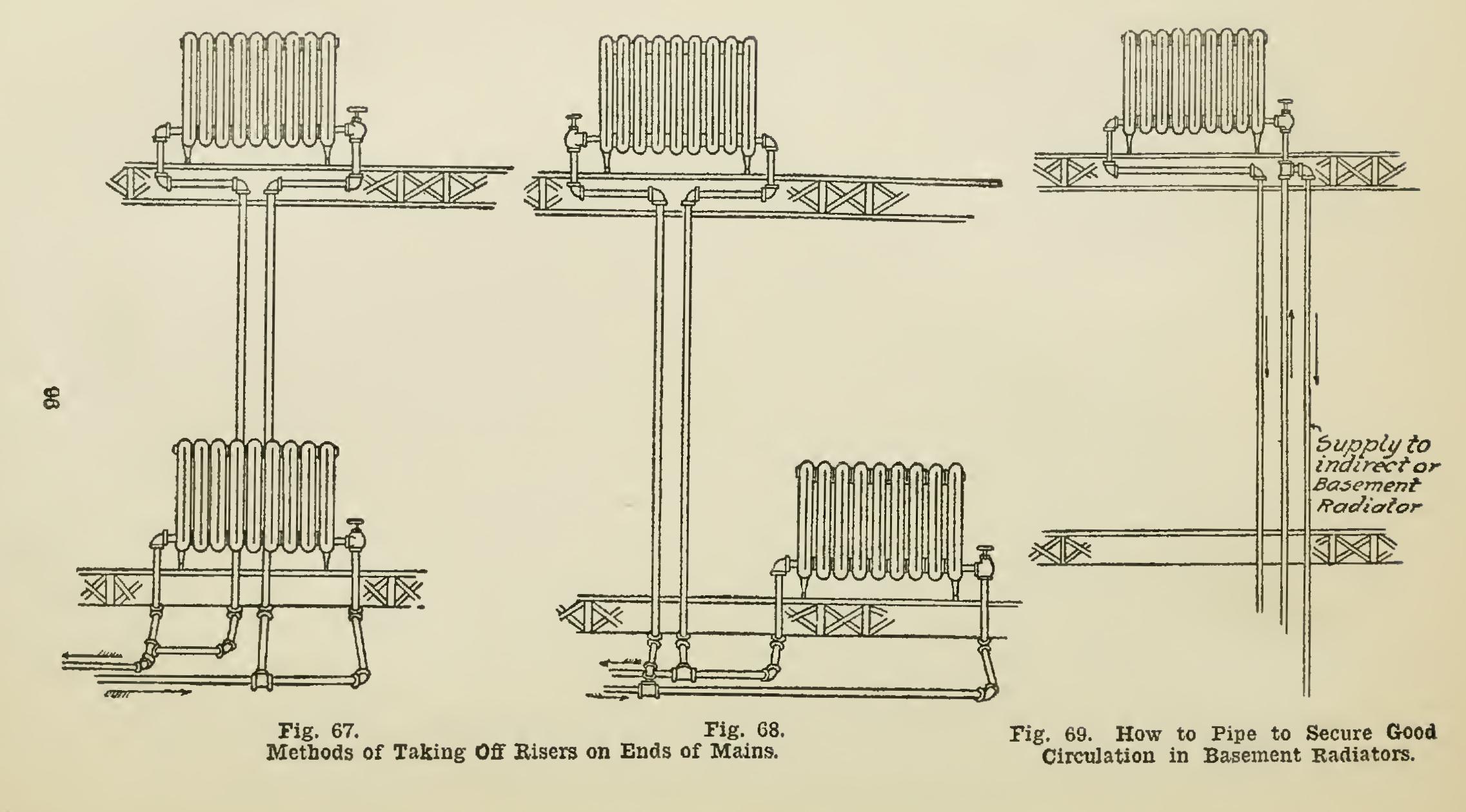
Piping for Accelerated Systems. Installa tions of accelerated systems call for radical changes in the method of making pipe connec tions. Owing to the small sizes of the piping, it is advisable to take all branches from the side of the main and to have them enter the side of the return, as shown in Fig. 65. The hot water will then flow to the end of each line before en tering the branches, for, as previously stated, the heated portion of the water always hugs the top of the main and each branch will receive its proper supply of hot water at about the same time. There are some modifications of this method, however. For example, when a branch near the heater feeds a riser to the upper floors without supplying a first-floor radiator, it is sometimes advisable to make the connection to the branch from the bottom of the main, as shown in Fig. 66. No riser should be taken from the end of a main, if such a connection can pos sibly be avoided. Take the connection to first floor radiator from the end of a main, and the branch to riser from the side of this connection. Figs. 67 and 68 show two methods of accomplish ing this, either one of which may be followed with success. In feeding basement radiators of either the direct or indirect pattern (described later), the supply should be taken from a riser at some point above the ceiling of the first floor; and the radiators should be fed from overhead by this drop pipe, as illustrated in Fig. 69.

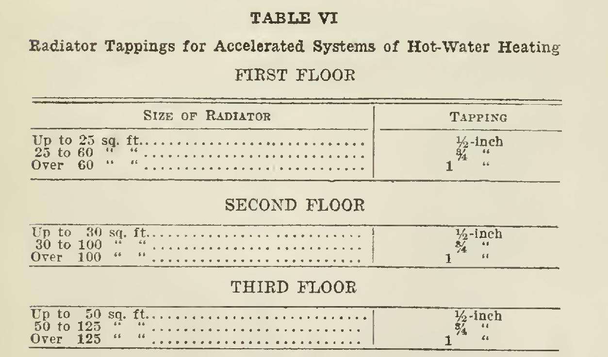
For accelerated systems the radiator tap pings are much smaller than with the usual in stallations. Table VI, showing the difference, will serve as a guide.
Although the radiation, with the accelerated system, may properly be reduced ten per cent, the heater installed should be of the same size as that required if placed on an open gravity system. It is considered good practice in con nection with an accelerated system, to figure on the use of a heater having a rating fifty per cent larger than the actual square feet in cast-iron radiation on the job, making the usual allowance for indirect or direct-indirect radiation.