Hot-Water Supply
water, pipe, tank, hot, valve, system, cold-water, boiler and street
This is the arrangement of a single heater for use in private dwellings; but in public buildings, such as a hospital, where a large quantity of hot water is needed, a storage system is used. Fig. 59 shows the installation for use in a hospital or other large building requiring a large volume of hot water. Connections are shown for a cir culating system of piping. A 300-gallon tank is suspended from the joists by means of lag screws turned up into the joists as shown at C. The hangers can be made by turning pipe into the desired shape. Left-hand threads can be cut on the ends of the pipe, and connected to the lag screws by means of right and left couplings (D). Two No. 6 Ruud heaters are used, one at each end of the boiler, and con nected up with brass pipe of the sizes indicated. The return pipe I is connected to the top of the manifold E.
At first glance, this seems to be against both theory and practice; but, as each individual coil is connected separately to the manifold, with a pitch of about 3 inches from one manifold to another, it is not so much against good practice as it seems.
The water supply F is connected into a re ducing fitting (S) in the manner shown, so that it will act on the injector principle, thereby in ducing a more rapid circulation when water is being drawn at the fixtures. On the circulation pipe L, 45-degree fittings are used, so as to offer as little resistance to the flow of water as possible.
Gas to the heaters is supplied through the pipe M, a globe valve N, being placed on each branch supply pipe at the most convenient point.
The hot-water supply pipe is taken from the top of the boiler, a blow-off valve being placed at B. This valve is set to blow off at a few pounds above the maximum street pressure, so that if the water gets excessively hot at any time, it will not expand back into the cold-water supply for the building. There is no check-valve shown on the return circulation pipe G, and it would be advisable to place a swinging check valve, with a light disc, at the foot of each rising line connecting into the main return line. If this is not done, cold or partially cooled water will be likely to work back up any one of the circulation risers; and, when the faucets are opened, the hot and cool water might mingle at the point of junction, so that, unless the water in the boiler is excessively hot, water only par tially heated might be drawn.
The smoke-pipes HH are to be connected to a convenient flue.
A careful study of the sketch and the descrip tion will make this type of heater perfectly clear.
Other types of automatic heaters are gov erned by the temperature of the water. After the heaters are set—that is, after the thermo stats have been set—a slight change of tempera ture in the water will automatically turn on the gas, which will burn until the water reaches the temperature for which it has been set; and then the gas supply will be automatically shut off, this operation being repeated indefinitely.
Either style of heater is very satisfactory, and, after being installed requires very little at tention, as all are what their name implies— automatic.
Fig. 60 shows a typical installation of hot and cold-water supply, with cold-water supply from street mains. As there is no place for the water to expand when heated, except back into the street mains through the cold-water supply, a check-valve should not be placed on the cold water supply pipe. Be sure and drill a hole in the boiler tube about one inch from the top of the boiler, and see that the spray from this opening does not shoot across the hot-water outlet and chill the outgoing hot water. By placing a valve on the cold-water supply to the boiler, the hot water may be shut off the system for the purpose of making repairs, etc., without interfering with the cold-water system. This is the common method of piping for the average installation in residence work, where the water supply is taken from the street mains, and the water can be heated by any of the methods here tofore described. If an automatic water-heater is used, the boiler and water-back may be omitted.

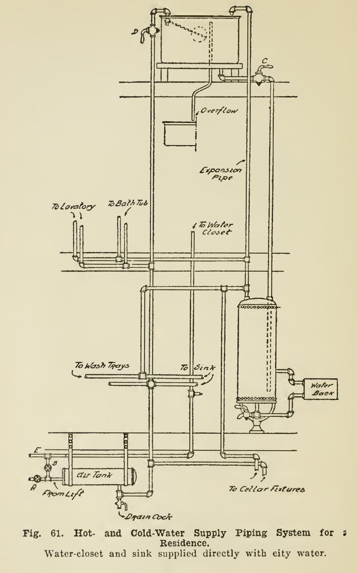
Fig. 61 shows a piping system in which the fixtures, with the exception of the water-closet and sink, are supplied with soft water, these two fixtures being supplied with city water. On the riser from the water-lift, at the attic tank, is placed a ball-cock such as is used in the tank of the water-closet, which maintains an established amount of water in the tank, and, when any water is drawn off, will automatically replace the amount used. The sketch shows the fix tures supplied with cold soft water, from the riser from the lift running to the tank; and the cold-water supply to the range-boiler is taken from the tank directly. When ordinarily used, the valve B is closed; but in case the soft-water supply gives out, closing valve A and opening valve B will admit city water into the entire piping system. The attic tank provides a re serve supply of water in case the city water is shut off temporarily. By cross-connecting the pipes D and C, and placing a check-valve on pipe E and the cross connection, when the pres sure goes off the riser pipe to the attic tank, the check-valve will allow the water from the tank to enter the piping system, and the check-valve at E will prevent the water from going out to the street mains, this operation being reversed when the city pressure comes on again.