Plumbing in Office Buildings
fig, water, waste, permit, fixtures, shown and urinal
\\There it can be used, Fig. 72 illustrates a Fig. 72. One System of Continuous Venting.

system of continuous venting that gives cellent results; but the location of the toilet room and the fixtures will not permit of this style in every job.
Both the soil- and vent-stacks extend up through the roof, and the arrangement of the pipe work almost entirely eliminates danger of siphonage. The main vent-pipe should connect to the soil-stack below the lowest set of fixtures, which will permit any dirt or scale in the vent pipe to drop into the soil-stack and be flushed through to the sewer.


Fig. 73 shows a floor-plan of a typical toilet room for buildings of this class.
The number and style of fixtures may be varied to suit requirements. The floor of the toilet-room is raised about DA feet above the hall floor, and this permits of the roughing-in, without any great amount of cutting or notching of timbers, and gives ease of access in case of necessary repairs or to clear stoppages. Clean out plugs are placed at convenient points to permit of easy access to the interior of the waste piping. The closet tanks go in the space be tween the stall partitions, as shown in Fig. 77.
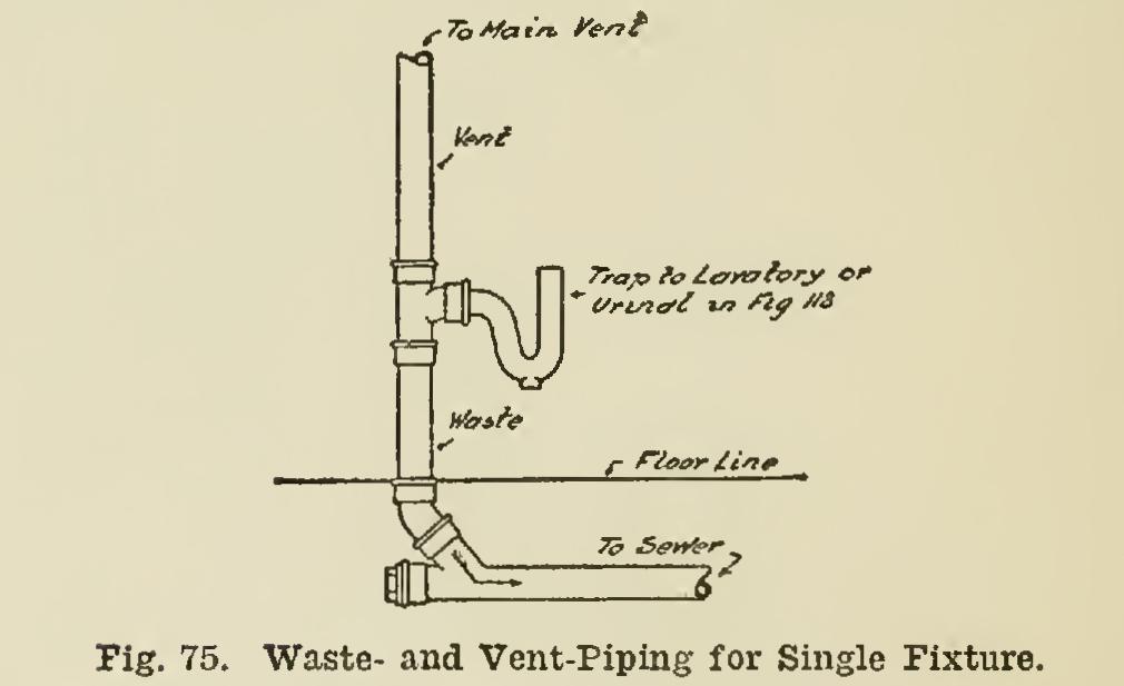
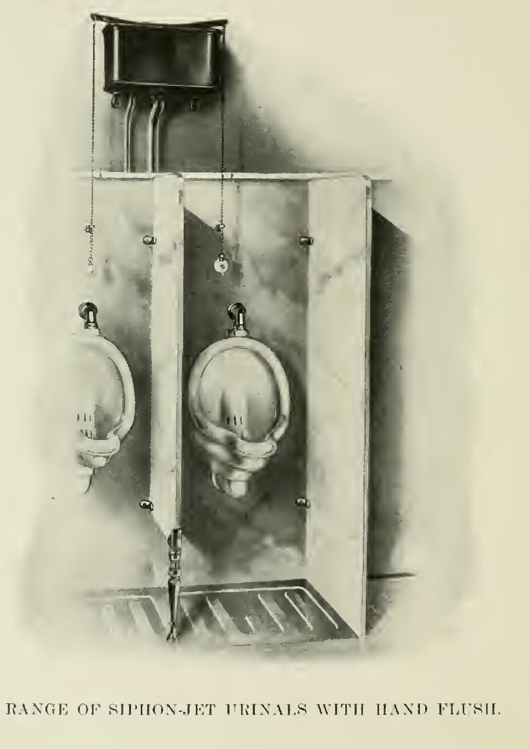
Fig. 74 is an elevation of the waste- and vent-piping for the urinals and lavatories. This style of venting does away with the possibility of the vents becoming clogged up, as might happen—and very frequently does—when the vent-pipe is taken from the crown of the trap.

Fig. 75 is an elevation of the waste- and vent-piping for a single fixture as shown in Fig. 74. The good points of this style of work can be readily noted.
Fig. 76 shows the ordinary method of vent ing a number of closets.
A comparison of Fig. 72 with Fig. 76 will show many superior points in the latter.
Fig. 77 is an end elevation of the closet stalls, and can be readily understood. Either high or low-down flush-tanks can be used. Sufficient room must be left between the stalls to permit of entrance for necessary repairs.

Fig. 78 shows a side view of the urinals. The system of waste- and vent-piping is shown in Figs. 74 and 75.
There may be a single automatic flush-tank for each urinal; or one flush-tank for the battery of urinals; or each urinal may be connected direct to the water supply, and be provided with a compression or self-closing urinal cock. The automatic tank is preferable, as it insures the urinals being flushed at regular intervals, and keeps them in a more sanitary condition. It takes water to keep things clean; so do not be afraid to use it; and this applies to the toilet room and its contents.

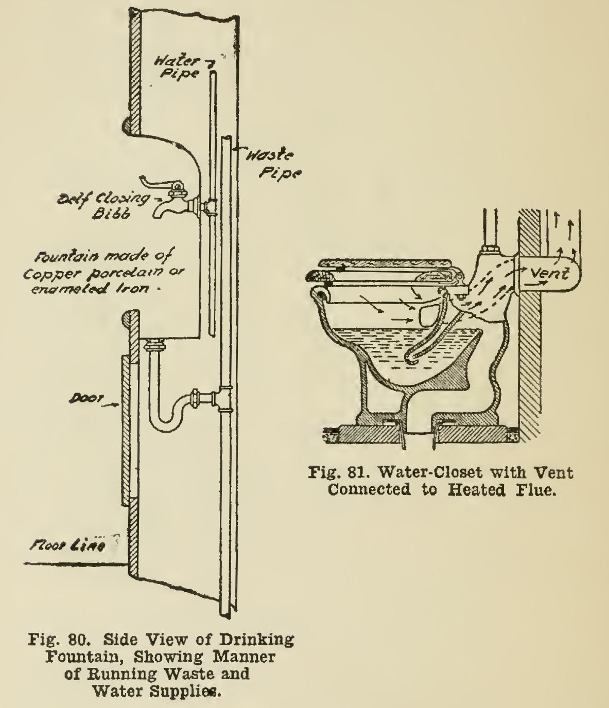
Fig. 79 is a side view of a porcelain urinal, and shows the manner of running the waste and vent-pipes. The vent-pipe in this case is carried to a warm flue; and this removes any odor from the fixture, besides tending to create a circulation of air through the toilet-room.
Fig. 80 is a side view of a drinking fountain, and shows the manner of running the waste and water supplies. This class of fixture does not permit of any great quantity of water entering the waste-pipe at any one time; so the danger from siphonage is slight, and the waste-pipe from the fountain can be branched directly into the waste-pipe as shown. The upper end of the waste-pipe should enter the main vent-pipe or be carried through the roof.
In some cases the water supply for the fountains is carried into a box which is filled with ice, sufficient pipe being placed in the box to allow a quantity of water to cool, which is then run to the fountains.
The main water supply for this class of buildings may be taken directly from the street mains. In case the pressure is light, or the building is a high one, it will become necessary to provide some means of forcing the water to the fixtures, and this calls for the use of a pump, with a storage tank above the highest fixtures, or a compression or closed tank in the basement. The pump, in either case, can be so connected that it will shut off when a certain height or certain pressure of water is reached, and will start automatically when the supply falls below this point. This pump can be operated either by steam or by electricity.