Systems of Reinforcement
column, steel, system, beam, umbrella, frame, head and concrete
In the Spider-Web floor and ceiling construction, all rods are small—usually three-eights inch to one-half inch in diameter, concealed in a continuous slab, and therefore fireproof. The octagonal hoop, which acts as a key to the eight trusses, is eight feet across. In buildings where columns are spaced twenty feet to centers the distance between column heads is twelve feet. The steel trusses comprising column head are usually formed of three quarter-inch round rods, and all pass through holes in the vertical steel forming core of the column. As com pared with ordinary beam construction, not only is the span, in effect, reduced, but the carrying capacity is further increased, because the spider-web pulls from all angles when loaded, whereas the beam construction pulls from only two directions.
Another system of the same general type of the Turner and the Barton systems is shown in Fig. 66 A and Fig. 66 B. This is the Cowles "Umbrella" System.

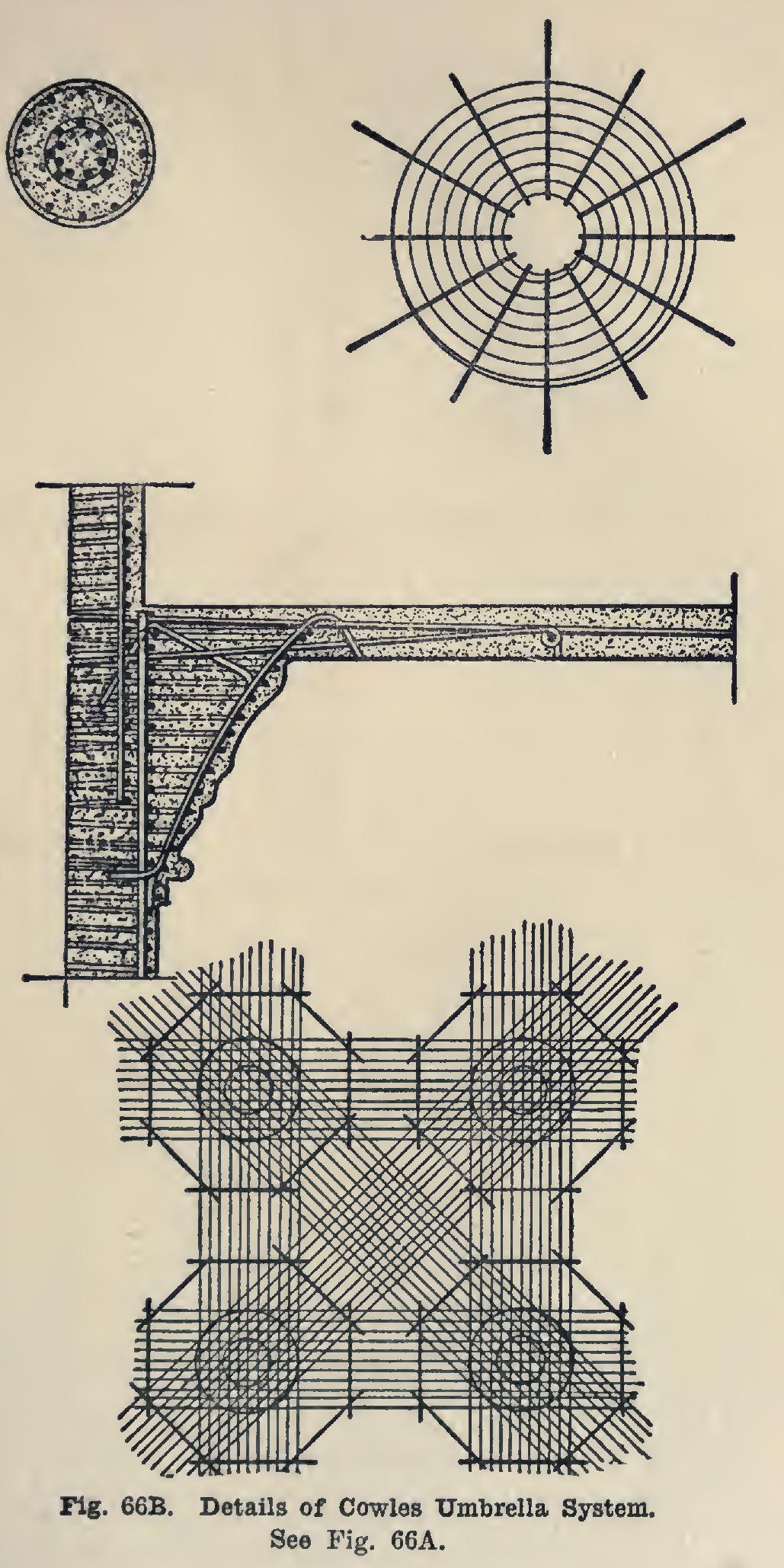
This system has for its object the doing away of the tee beams frequently used in reinforced concrete con struction, and the substitution therefor of flat slabs inte gral with the supporting column. The construction, it is claimed, is not only economical, but gives maximum strength with minimum material.
This system is a departure from other systems of this general class in that the columns are continuous, and, if spliced, a telescope splice is used in the umbrella head, which has triple hooping reinforcement. Not only is the value of the umbrella head thus increased threefold, but the column loads from above are substantially transmitted into the center of the column below, thereby insuring a continuous column and minimizing the danger of eccentric loading of the lower column.
Another distinctive feature of this construction is the cantilever compression rods. These rods lie directly beneath the tension or slab rod, and are so distributed as to strengthen the concrete in compression at the per imeter of the umbrella head. They also help the slab at this point in shear, and at the same time help to restrain the concrete in the bottom of the slab forming the top of the umbrella head.
A still more interesting feature of this system is the umbrella basket, which is designed to reinforce the umbrella head in shear and also to restrain the entire concrete forming the head. This basket can be assembled and spirally wound, at the shop, preferably upon a machine built for the purpose.
The size and amount of the various steel sections used in this basket depend upon the loads to be carried. This statement, of course, applies also to all of the steel form ing the structure.
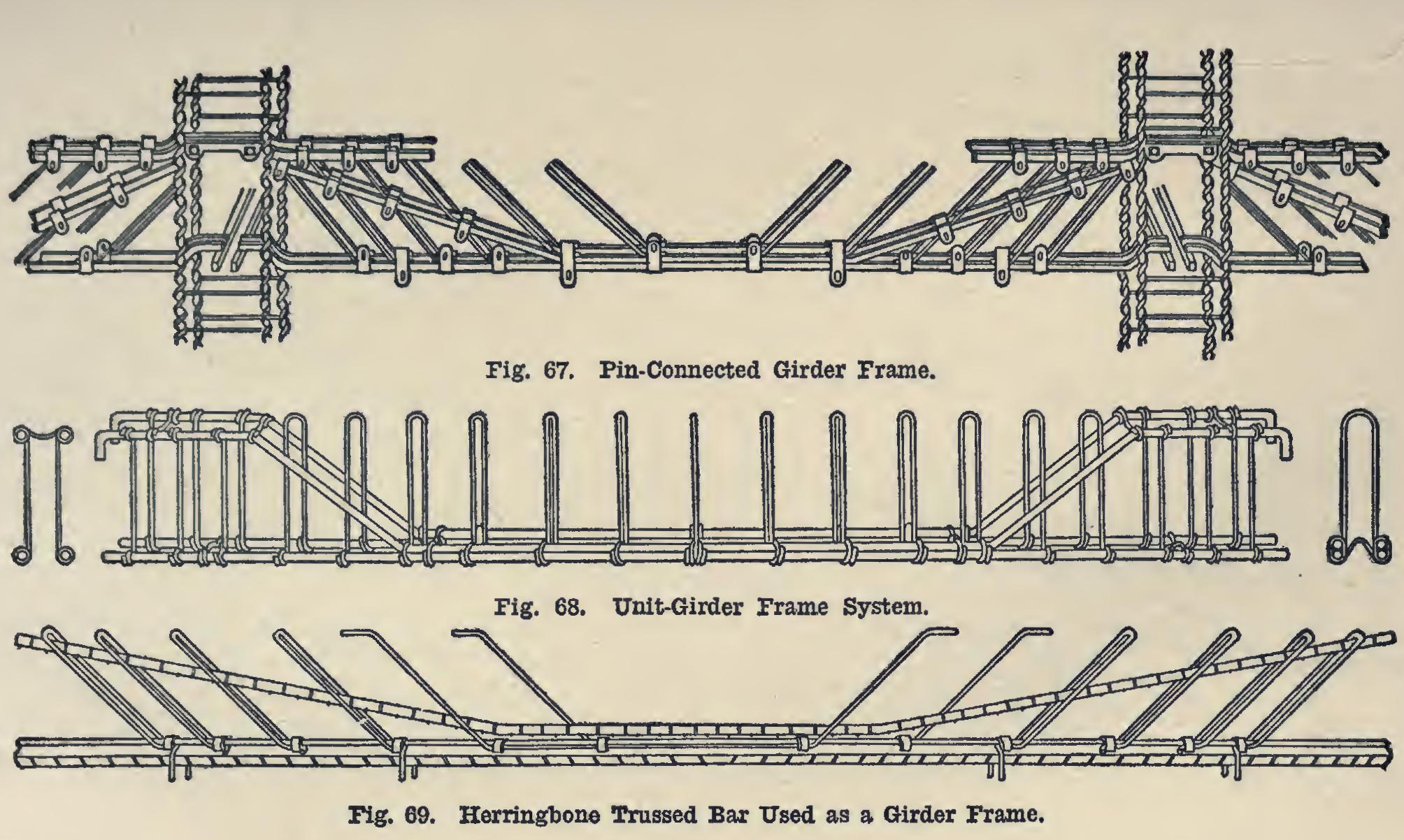
As an example of the Unit-Beam System of reinforcement, the Pin-Connected Girder Frame, as shown in Fig. 67, is given. These frames are shipped from the manufacturers ready to be lifted into the forms. No expen sive field work, either blacksmithing or assem bling, is required. Each frame is so numbered that the steel is erected rapidly and economi cally; and the dangers of misplaced steel, which always attend the use of loose rod reinforce ment, are entirely avoided. The mechanical features pointed out as of greatest importance are: Diagonals rigidly attached at both ends, which may be spaced as frequently as is necessary to resist the shearing stresses; Carrying one of the main members to the top at the supports, and returning it to provide for negative moments ; A link and pin connection over each point of support, giving each frame a mechanical connection with adjoin ing frames, so that bonding action of the concrete is not depended upon to transmit stresses from beam to beam.
In use as beam reinforcement, the required amount of steel is made up by using as many frames (units) as are necessary. In the construction of these units bars are used, varying by sixteenths, from % of an inch to inches.
Another specimen of this same type of rein forcement is the Unit Girder Frame, shown in Fig. 68.
Fig. 69 shows a Herringbone Trussed Bar used as a unit-frame.
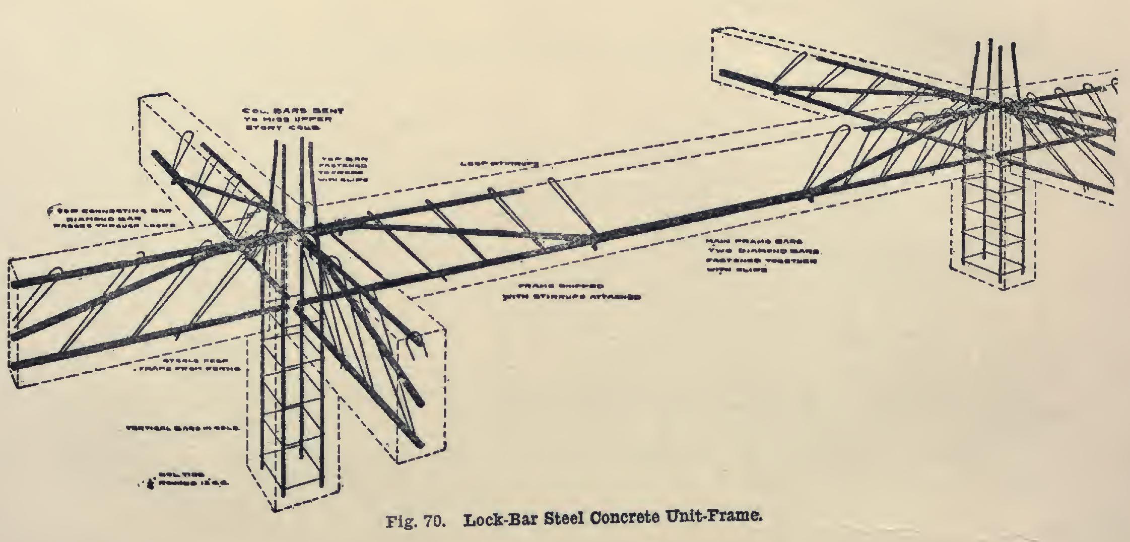
Fig. 70 shows a type of unit girder and col umn frame—the Lock-Bar Steel Concrete Unit Frame.
The essential feature of this system is the shop-made girder and beam frame. A special feature is the loop stirrup, which is tied mechanically and by adhesion, at both the top and bottom, and which is accurately and rigidly fastened in the shop.
The cut shows a beam between columns, reinforced by a single frame. The two bottom bars with stirrups attached are shipped in a unit as shown, ready to set in place. Two adjacent frames being in place held up from the forms by stools of proper height already attached, the top bar is passed through the loops of the stirrups and clamped above the bent bars. The reinforcement is then in place accurately and rigidly.