Systems of Reinforcement
steel, concrete, system, beam, floor, reinforcing and construction
The bars used are diamond-shaped, with ribs for a mechanical bond, and are set one above the other on their points, and in the direction of the short diameter of the diamond. This serves to reduce the height of the rein forcement, and the ribs serve to keep the bars apart so that the concrete is certain to reach every face of the bar.
By the use of various sizes of bars in the frames, vary ing from 1/2 in. to in., and by the use of any number of frames in a beam, the reinforcement can be regulated and accurately designed and laid out to meet varying conditions.
For column and slab rods, a round-edge and concave sided bar is used, which may be plain or twisted as required.
Fig. 71 shows the System M form of rein forced girder and beam construction. This sys tem consists of an independent light steel frame, which is subsequently so united to concrete that the two become a reinforced construction.
The upright iron or steel supports and the steel floor members can be formed with sections of any shape suit able to make a light, independent structure capable of maintaining its form. The steel uprights are erected plumb and the steel floor members are set level. The girders are connected to the uprights to keep them plumb, and the floor-beams are connected to the girders to make a sufficiently rigid structure.
This steel frame forms the guides for the erection of the wooden or other moulds into which the concrete form ing the floors, and forming the covering of the uprights, is to be poured. The reinforcement cannot be displaced or misplaced by careless workmen.

Although any kind of steel section which is sufficiently stiff can be used for floor members, and several kinds of special sections offer best theoretical results, still good, practical results have been obtained by the use of small I-beams and channels. The size of the I's and channels used, it is claimed, is usually not more than one-half the height of the steel beams required, for ordinary construc tion, to carry the entire floor load. In this system the smaller the height of the steel members (in concrete beam of the same depth), the greater the economy of steel, on account of the increased effective depth of the reinforced concrete beam.
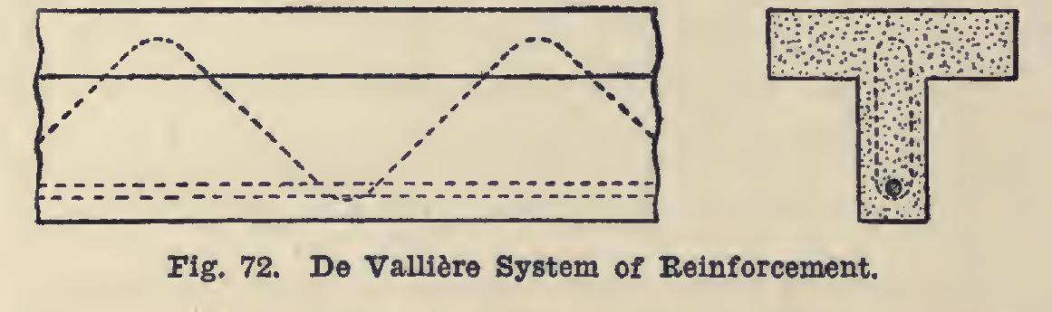
The De ValHere System for beam and girder construction is shown in Fig. 72. This system
consists of a main reinforcing bar located near bottom of web, and surrounded by a spiral coil of heavy wire.
The Hennebique System is founded upon the principles advanced by Francois Hennebique in the early stages of reinforced concrete work. Fig. 73 shows the general plan of arrangement of reinforcing. Other views of this system are given later under "General Building Construction." In the Hennebique beam the concrete is relied upon to resist the compressive stresses in the upper part of the beam, while the steel rods resist all tensile stresses in the lower portion. The concrete also forms the con nection between the two flanges, assisted by the stirrups, generally formed of hoop steel. These are of great impor tance. Besides acting as a connection between the upper and lower parts of the beam, they take also the horizontal shear. For this reason the stirrups are placed closer together near the supports.
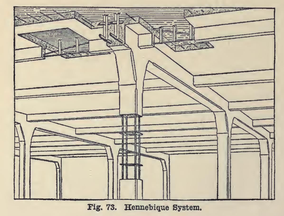
The rods in a beam are of two kinds—straight and bent. The bent rods, besides taking their proportions of the direct tension and of the shear, take any tensile stresses in the upper portion due to a negative moment over the support. A beam of this description is similar in many respects to a timber trussed with steel tie-rods and brackets.
The Merrick System for reinforcing floors is shown in Fig. 74. The object of this system is to lighten the weight of the concrete slab. Di rectly upon the forms a 2-inch layer of concrete is placed; and, before this has set, oblong boxes of metal fabric of small mesh are laid horizon tally, with the reinforcing rods in the spaces be tween them, and the concrete is filled in between the boxes and around the reinforcing rods, and covered over the top to form the floor.
The Roebling System (see Fig. 75) is em ployed in connection with a structural steel frame of I-beam or girder construction.
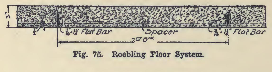
For all flat construction of floors, the reinforcing system used consists of flat bars placed upon edge, secured at the ends to the steel beams and bridged with bar separators. The object of the edgewise position of the bars is the increased protection thus secured to the rein forcing steel. With this type of floor the structural steel frame is generally completely encased with concrete.