Systems of Reinforcement
joists, concrete, fig, wood, floor, bars, laid and system
The joists are laid in the building with the flanges touching, forming a continuous and complete surface on top to hold the finishing floor. Any type of floor—plain cement finish, tile, granolithic, or wood—can readily be laid on the joists.
The under side of the joists forms another complete and continuous surface for the ceiling, requiring but a single coat of rough plaster on which to place the final finish.

The hollow space between the joists forms a con venient space for the laying of pipes, wires, etc., as well as providing a large air space which prevents dampness, sound-proofs the floor, and acts as a non-conductor for heat and cold.
The use of this system does not limit in any way the other structural features of the building. Any wall can be used except the ordinary wood studding, which, of course, would not be suitable for fireproof floor construc tion. The use of two-piece concrete blocks, using them only on the inside as a bearing wall for the joists, makes a specially good and cheap wall. The outside may be veneered with brick, concrete blocks, or tile, or finished with metal lath and stucco as may be desired.
For intermediate supports a simple construction is the use of steel I-beams and cast-iron columns.
The joists are cast on the ground, either at a plant established for the purpose, or may be made at the point where they are to be used. Made in forms of wood or pressed steel, readily admitting variations in length, and, if necessary, changes in depth and proportions to meet different conditions of loading, they present a form of concrete construction adaptable to greatly 'varying con ditions.
After curing from 20 to 30 days, the joists are ready to be placed in the building, although, as in all forms of concrete construction, they will keep on increasing in strength for a much longer period.
This method of construction does away with all false work, staging, or centering, the use of hollow tile, etc., for filling. A still further saving is due to the absence of all obstructions in the interior of the building, and in consequence the opportunity to push the inside finish rapidly.
Fig. 79 shows the Vaughan system joists used with an I-beam for the intermediate sup port. The cement shoe tile shown are a stock product. They are cast in two sections, and form a fireproofing coat for the beams as well as a support.
In factories and warehouses, a layer of con crete one inch in thickness on top of the joists is all that is necessary to finish the floors. When a wood floor is required, it can be readily placed as illustrated. A grillage of light wood strips
is laid directly on the joists, and a layer of wet concrete poured in between to hold them in place. This leaves a space directly under the wood floor for the passage of pipes, electric wires, etc.
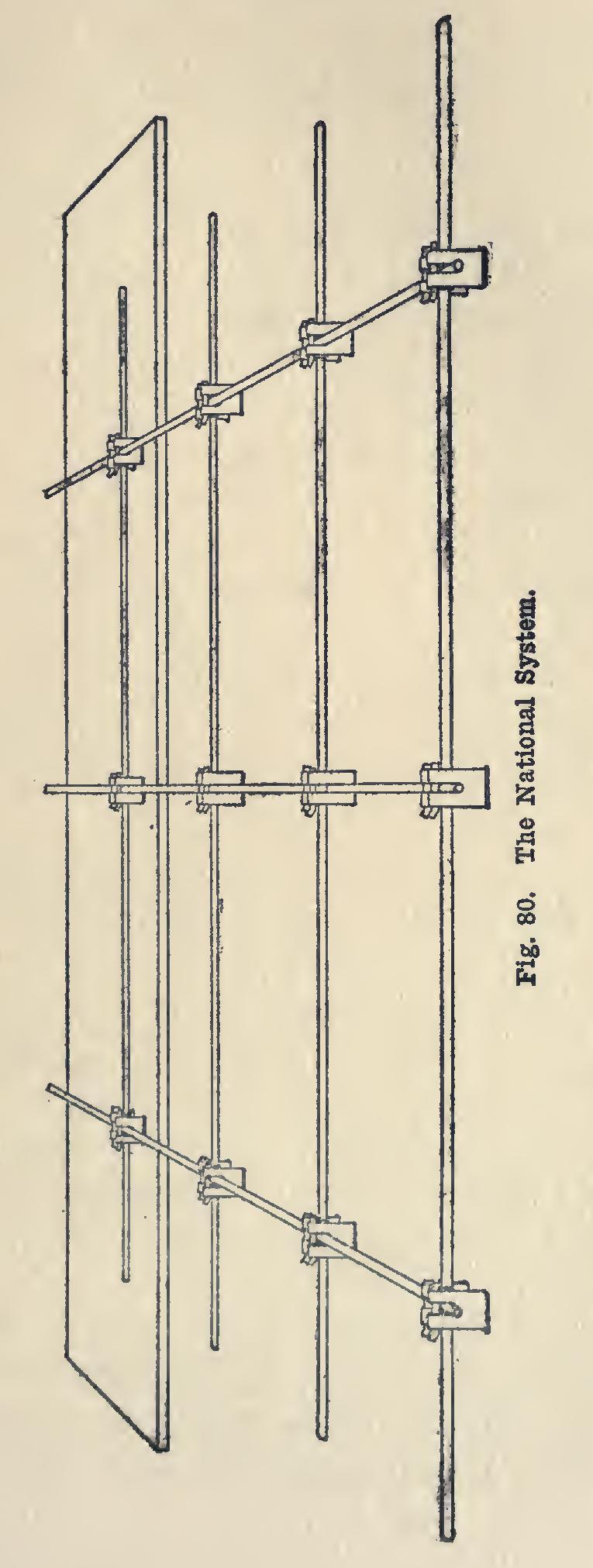
The National System for the reinforcement of concrete makes use of a special device for locking the rods or bars together.
Fig. 80 shows the rods or bars in place, fastened together with the National Chair, on the form. No part of the rods or bars, either cross or longitudinal, rests upon the form, thus permitting them to be thoroughly im bedded in the concrete.
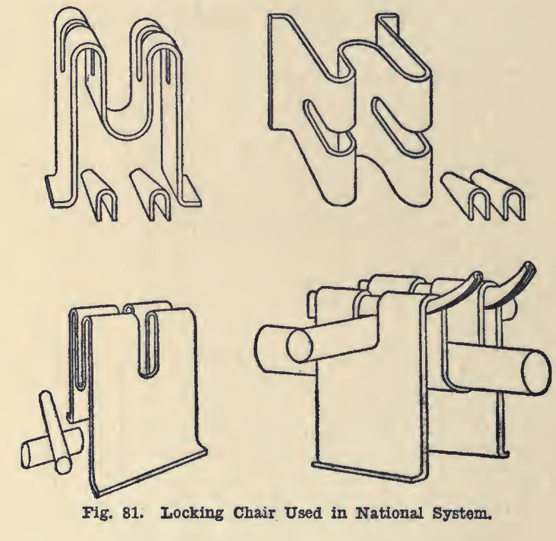
Fig. 81 illustrates the "chair" for locking the heavier wires and bars, the lower right diagram showing it assembled with the wedges turned up, making a perfect lock. The wedges are turned up with a very simple tool. The cut also shows the feet of the chair which keep it from sinking into the form. In spiral or column construc tion the feet of the chair are absent.
The above systems are a few of the many in use for reinforcing the superstructure of a building—that part above the foundations. The methods of reinforcing foundations and footings for buildings resting upon soft or unstable ground may be considered as coming under two classes: 1. When the footing is to be spread out wide enough so that the allowable pressure per square foot of bearing area is a safe amount for that particular soil; 2. When concrete piles are used to obtain the same result with the use of less horizontal bearing area and a corresponding lessening of materials used.
Since the load upon a spread footing com monly comes on its center, especially in the case of columns, some means must be used to dis tribute that load evenly over the under side of the footing, and also to provide for any bending action which may occur in the wide flat surface on account of the concentrated central load. A common way of providing for these necessary points is by the use of rods, bars, I-beams, T-beams, old steel rails, etc., laid in a form of grill work and embedded in concrete. Some times they are simply laid at right angles to each other as shown in Fig. 82 and Fig. 83; and at other times diagonal layers are used, in addi tion to the former layers.
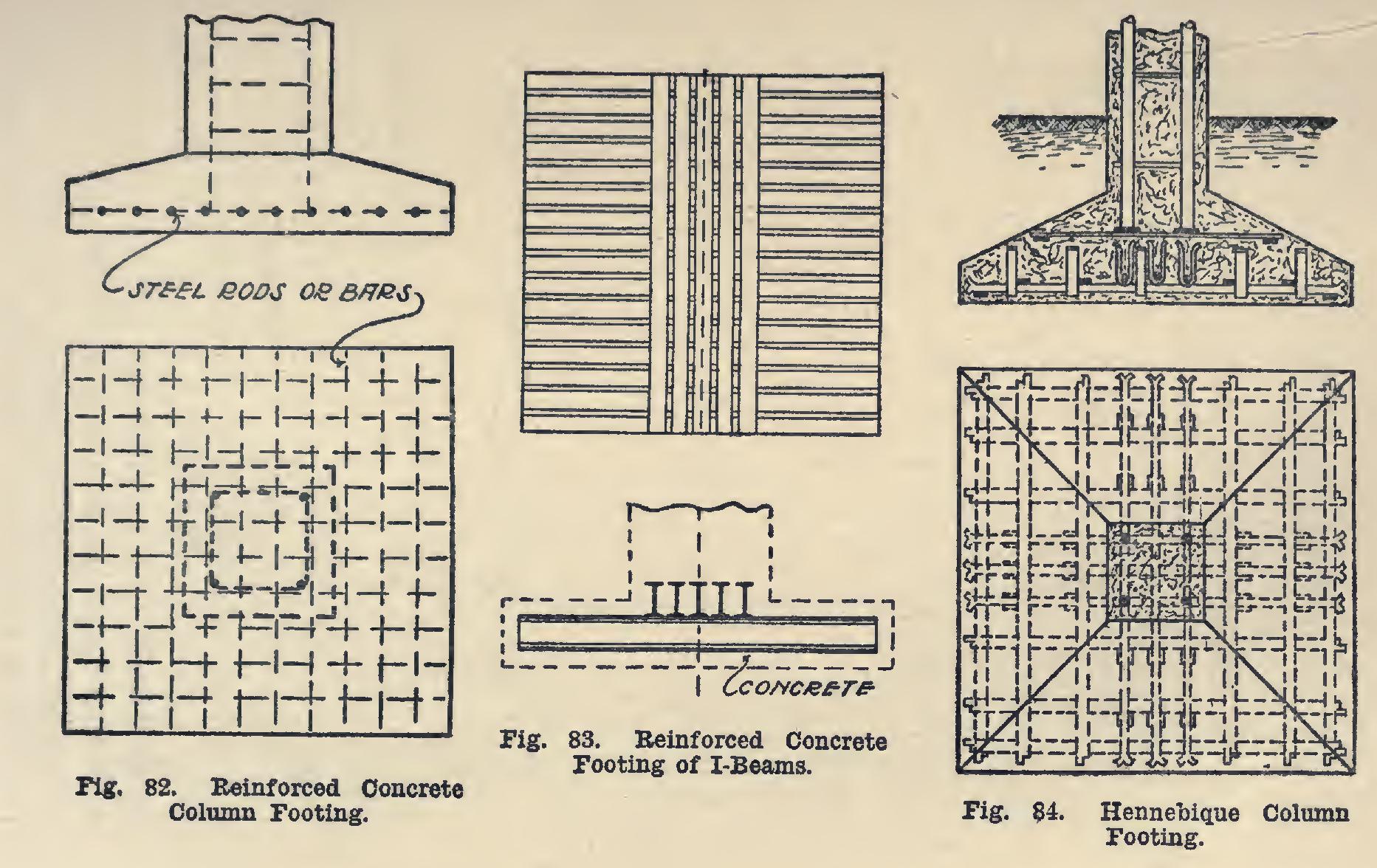
These footings do not need to be made of an equal thickness throughout, as the greatest bending action will tend to come near the middle; therefore it is common practice to make the edges of the footing thinner than the central part.
Fig. 84 shows the Hennebique system of column footings.