Systems of Reinforcement
system, shown, bar, construction, bars and beams
SYSTEMS OF REINFORCEMENT Although we have referred in a general way to the use of various forms of steel as reinforc ing agents, architects and engineers have begun to use these materials in more or less advanta geous grouping of parts. The following systems illustrate a few of the combinations which are in use in building construction to-day. Most of these are the results of careful computations by competent men, and some have been thor oughly tested by severe conditions in construc tion work.
The Ransome System is one of the pioneers in the line of reinforcing concrete floors and beams by the use of rods. This system con sists of reinforced beams, quite thin and deep, with web stiffeners, spaced about like floor joists in ordinary construction work, and supported by girders at the ends. Several bars are grouped in parallel layers for the heavier girder rein forcements. In the case of long spans in the beams, a central stiffening web is often used as bridging between the beams. See Figs. 61 and 62 for details of construction as applied to the Pacific Coast Borax Refinery at Bayonne, N. J.
The Kahn System of reinforcing by means of the Kahn Trussed Bar is shown in Plates 14 and 15. The detail of this bar is shown in Fig. 50. This system really consists of what may be considered as a large number of separate mem bers all rigidly attached and handled as a unit. The labor saving in handling a single piece as compared with many separate individual parts, is one of the advantages claimed for this system.

The Kahn trussed bar is made of a special grade of medium open-hearth steel with an elas tic limit up to 42,000 pounds and an ultimate tensile strength of 70,000 pounds. The cross section illustrated has two horizontal flanges or wings projecting at diametrically opposite cor ners. These winged portions are sheared up at intervals and bent so as to make an angle of 45 degrees with the main portion of the bar. It is claimed that in this bar there is no waste metal at any point and proper reinforcement is provided at every place it is needed. For in stance, in the central portion of the beam where the full section of metal is needed for bending moment, and no reinforcement re quired for shear, the bar is unsheared and the full area of the metal is available. At the ends
of the beam where the shear is a maximum and the bending mo ment a minimum, the flanges of the bar are struck up to form rigid ly attached shear mem bers which carry the shearing stresses direct ly to the main tension member.
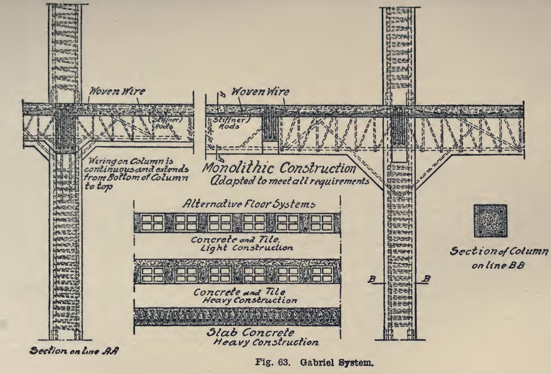
The Gabriel System of reinforcing beams, floors, and columns, is shown in Fig. 63.
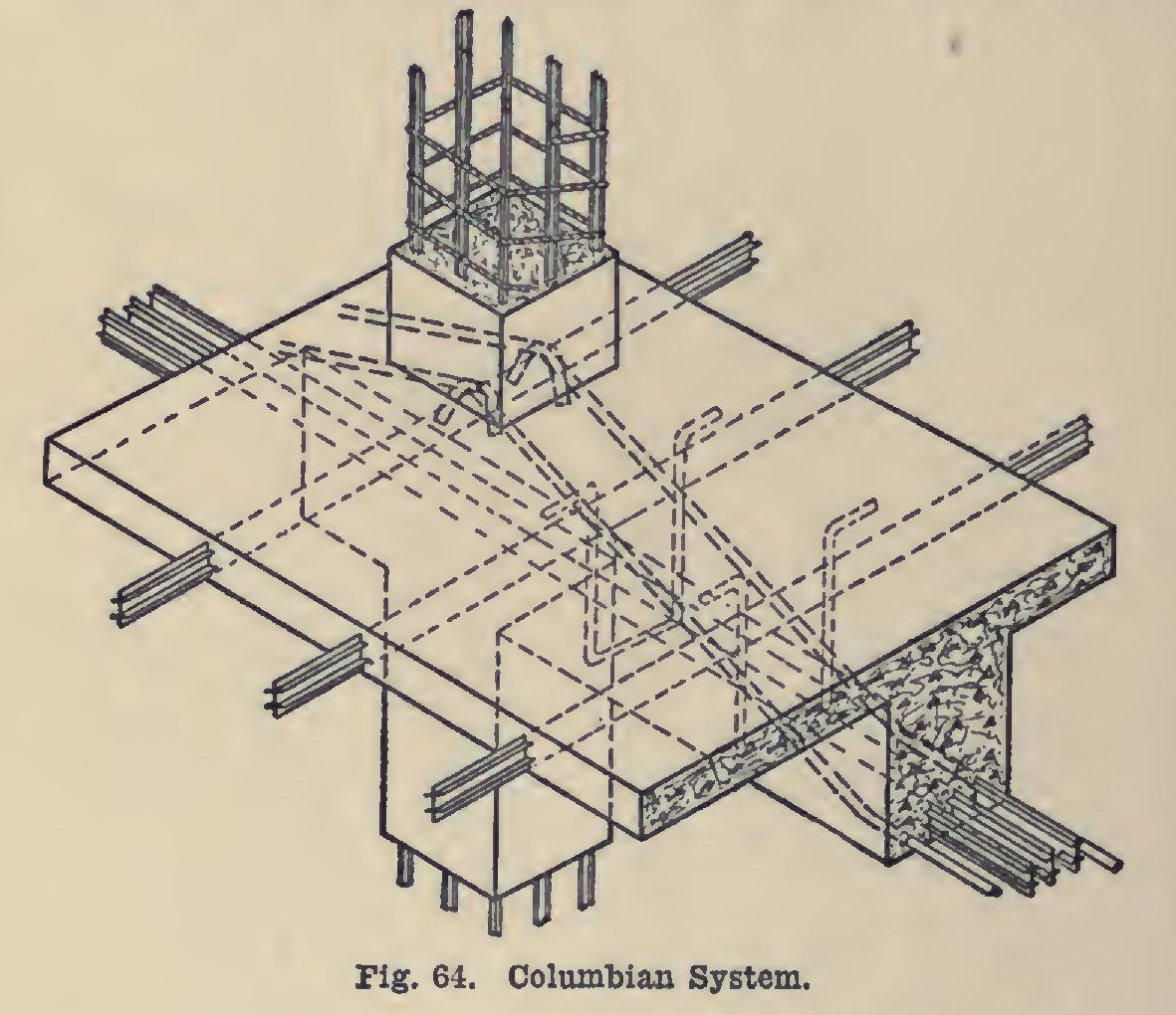
The Columbian System is shown in Fig. 64. The special forms of Columbian bars, and the methods of placing them in slabs, girders, and columns, are clearly illustrated.
The Cummings System, invented by Mr. Robert A. Cummings, is in this special bar class. A number of reinforcement details are illus trated in Fig. 65. At the top of the diagram is shown the Cummings method of forming the bent-up bars and attaching them to the tension bars. In general the plan is to provide tension bars with ends specially anchored; while se, curely attached to them are small rods hori zontal in the middle of the beam or girder, but bent up, as indicated, to pass across the top of the beam and form inclined inverted U-bars or stirrups. The idea is more clearly shown in the sketches below of "Arrangement of Steel." The "Supporting Chairs," placed at the point of the bending up of the rods, are also drawn. For the slab steel, another type of supporting chair is employed, as illustrated in the detail sketch.
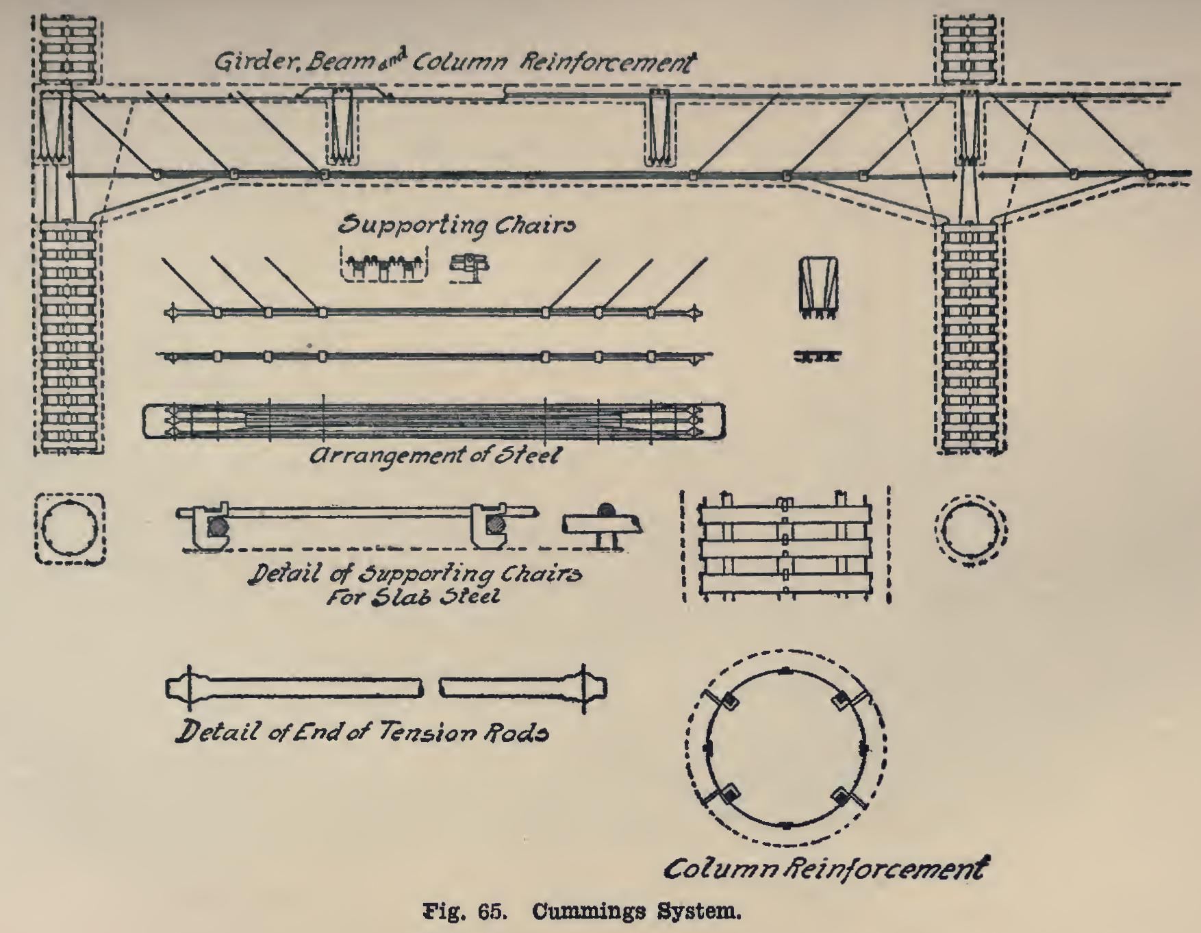
The Cummings hooped column is also shown in the upper sketch, and the details of the column reinforcement below. Each hoop is securely attached to the upright rods.
Plate 16 shows the Mushroom System of flat slab construction. The rods run between the columns both transversely and diagonally as shown in the figures. Another view of this sys tem as applied to column construction is shown in Plate 19, in the section on "General Building Construction." This system is the invention of Mr. C. A. P. Turner, of Minneapolis, Minn.