Hoppers and Hopper Bevels
line, bevel, miter, shown, draw, tongue and plan
Another method generally employed for find ing the bevels of hoppers is to bevel the top and bottom edges of the sides and ends to the angle they are to stand at, then to lay a bevel set to a miter, or angle of 45 degrees, on the beveled edge, and that will lay off a miter joint, while a try-square will lay off a butt joint; otherwise an angle of 45 degrees will miter only those boxes with sides which are vertical and square with each other.
When a hopper has the sides and ends of different widths, that is, when sides and ends stand at different angles, both having the same rise, find the cuts for each from its respective rise, run and width.
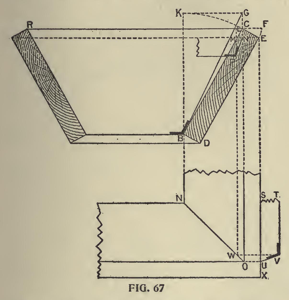
In the preceding it has been shown how the bevels and lines for hoppers may be obtained by the aid of the square, and it is now proposed to show how the same results may be obtained by a sys tem of lines. This method, in many shapes and forms, has been used from time immemorial by workmen, more particularly by carriage makers to obtain the bevels of splayed seats; the present way of expressing it is, however, comparatively recent. If we make Al, Fig. 66, represent the elevation of our hopper, and Bl a portion of the plan, we proceed as follows: Lay off NS, which is the bevel of one side, and NSPO the section of one end.
Place one foot of the dividers at N, and with NS as radius describe the arc SU, intersecting the line NU in the point U. At S erect the per pendicular ST, and draw the line UT at right angles to NU. Connect N and T; then the triangle MNT is the end bevel required. The line NT is the hypothenuse of a right-angled triangle, of which NU may be taken for the perpendicular and UT for the base. To find the miter of which DE is the plan, project S and P, as indicated in the plan by full lines. With SP as radius and S as center, describe the arc PR. In the plan draw DG, on which lay off the distance SR, measuring from F, as shown by FG. Then GHF is the miter sought.

Fig. 67 shows the rule for finding the bevels for the butt joint of the hopper. From M, the point at which EM intersects BC, or the inner face of the hopper, erect the perpendicular ML, intersecting RF, or the upper edge of the hopper, in the point L. Then LC shows how much longer the inside edge is required to be than the outside. In the plan draw TV parallel to SX, making the distance between the two lines equal to CF of the elevation, or, equal to the thickness of one side. From the point L in the elevation drop
the line LW, producing it until it cuts the miter line NO, 'as shown at W. From W, at right angles to LW, erect a perpendicular WV, meeting the line TV in the point V. Connect V and U; then TVU will be the angle sought. This bevel may be found at once by laying off the thickness of the side from the line EM, as shown by NP in the elevation, and applying the bevel as shown. This course does away with the plan entirely, provided both sides have the same inclinaton.
There are several other ways by which the same results may be obtained, and some of these will no doubt occur to the reader when laying out the lines as shown here.
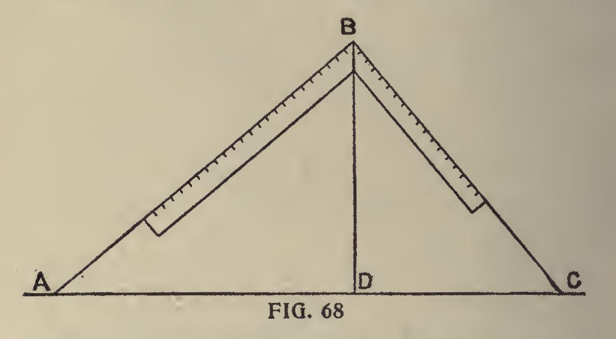
In Fig. 68 is shown another method for finding the bevels for a square or rectangular hopper. Let AB always be the guiding line, and the one from which all the others take their positions, making that line equal in length the width of the side of the intended hopper.
To find bevel to cut across face of board: Take AB on blade and AD on tongue; bevel of tongue is the line required.
To find miter: Take AB on blade and BD on tongue, line of tongue is bevel sought.
For butt joint: Take BC on blade and AD on tongue, and line of tongue gives bevel required.
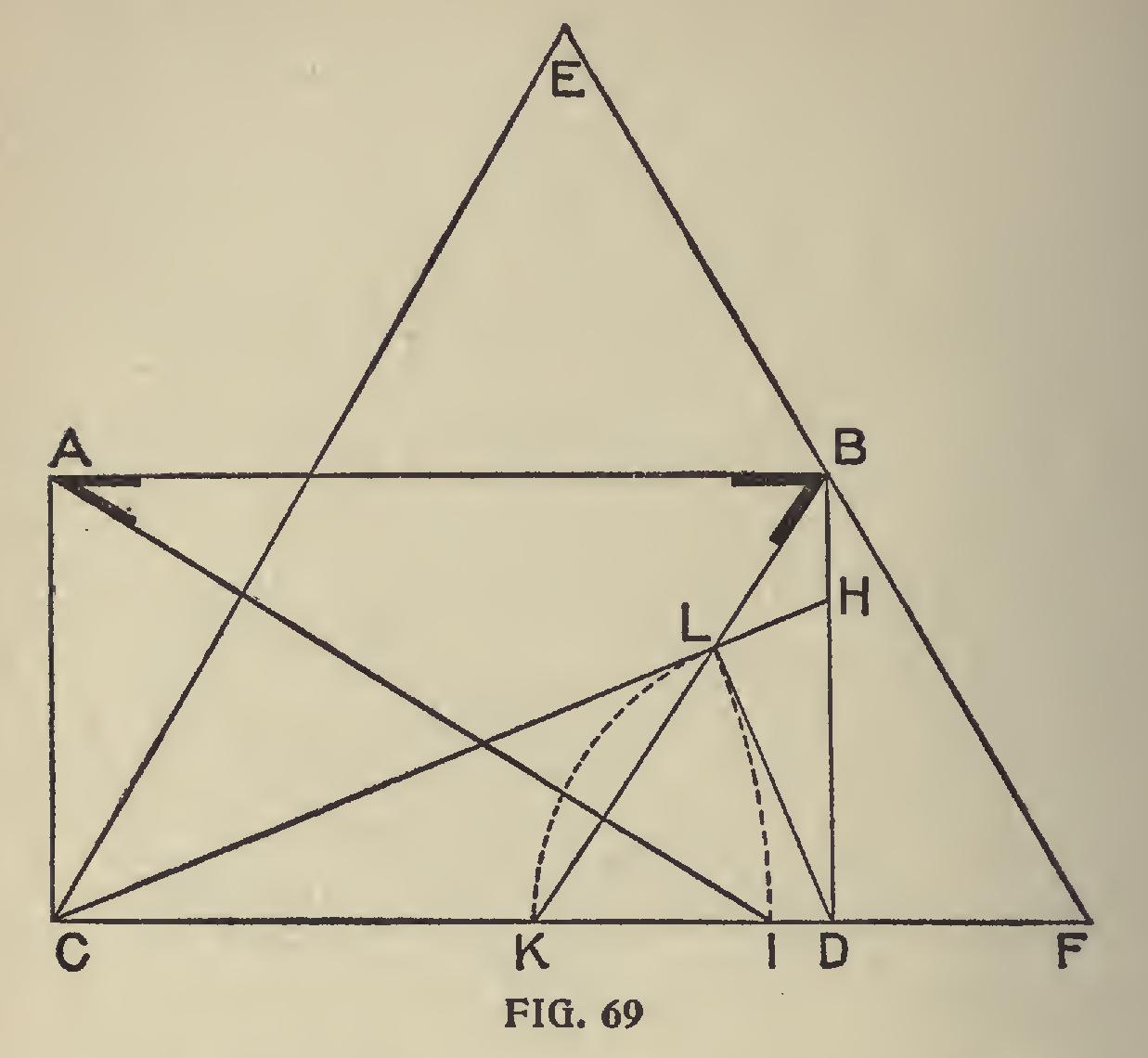
Cuts and
Bevels for Flaring Hopper.—In order to make this department complete, we herewith give a method by which the cuts or bevels may be obtained for a flaring hopper having only three sides. In other words, Fig. 69 gives bevels for a box whose top and bottom form two unequal equilateral triangles: Make the triangle CEF, then from the middle point of EF let fall the perpendicular BD, then draw AB parallel and equal to CD, also AC parallel and equal to BD, thus forming the rectangle A, B, C, D. Now draw CH to the same inclination from CD, that a side of the box when finished will show from the perpendicular line; then draw LD perpendic ular to CH, and, with C as a center and a radius CL, make an intersection at I, and connect I and A, and at A is the bevel for the miter at the ends. Again with D for a center and a radius DL, make an intersection at K, and connect K and B; and at B is the bevel for the down or cross cut.