Hoppers and Hopper Bevels
shown, brace, square, cut, blade, tongue, braces, angle, beam and length
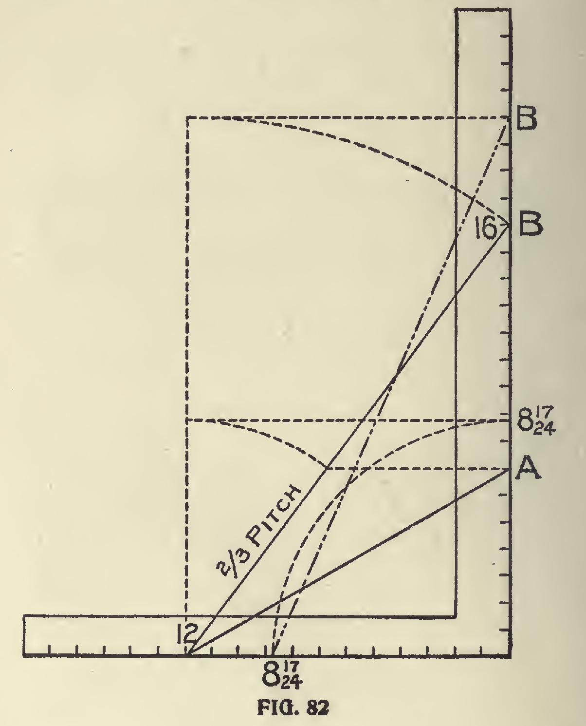
First method is shown in Fig. 82. We wish to make a hopper two-thirds pitch or 16-inch rise to the foot in run; 12 and 16 give the hypoth enuse or pitch and is 20 inches in length. Next we take 8 and 17-24 on the blade because that is the tangent for the pentagon just the same as 12 is for the square figure. Then with 8 and 17-24 for radius describe an arc from 12 cutting the pitch line as shown; thence carry this point to the blade as at A; 12 on the tongue and A on the blade will give the miter across the edge of the board; the latter giving the cut. 8 and 17-24 transferred from the blade to the tongue and 20 on the blade will give the cut across the face of the board.

In Fig. 83 is shown the second method: In this it will be seen that the same figures are used as in the first method for finding the miter cut.
In this illustration we show two squares with their tongues together. The side cut is found the same as in the former figure, but in this another pitch is shown and which we will call the co-pitch. This pitch stands at 90 degrees from the given pitch of the hop per, provided the tim ber is square edged or at right an gles with the side (though it may be at any angle). The rule is: Take the length of the co-pitch on the blade and 8 and 17-24 on the tongue and the latter will give the miter. This rule ap plies to any polygonal hopper. The figures to use on the tongue are always 12 and those that give the miter for a polygonal frame.
In the case of a square hopper the tangent is equal the run (12) and for that reason only one set of figures on the tongue is used.
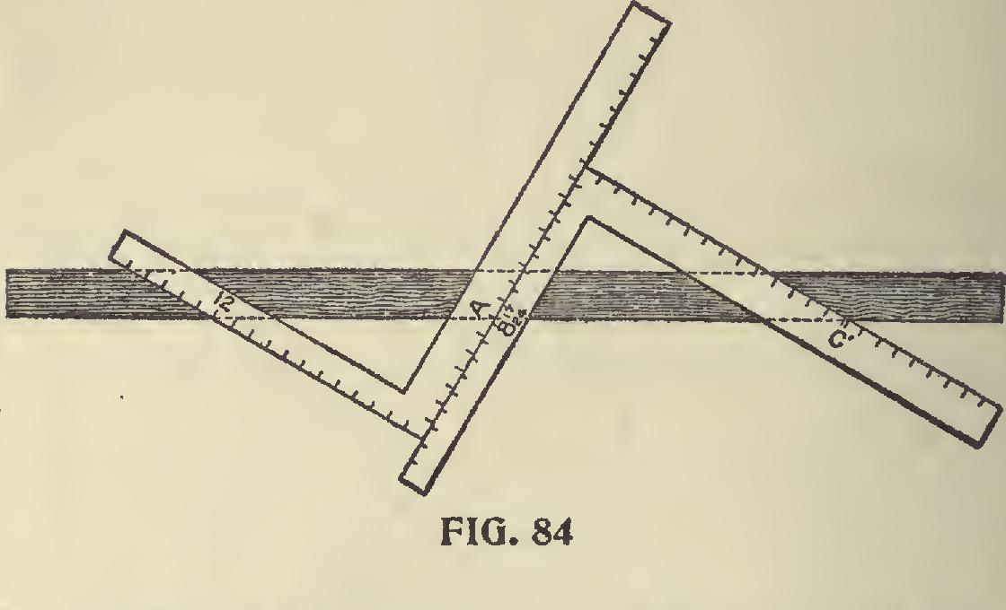
In Fig. 84 is shown a proof of the two methods. The blade giving the cut in the former and the tongue in the latter.
Trusses.—In taking up the subject of trusses it is not our intention to enter into the subject further than the application of the Steel Square in obtaining the cuts and bevels. The rules for finding the cuts and bevels for common rafters and braces will apply to truss work in general.
In Fig. 85, A is the straining beam, B the brace, T the tie beam. Generally the brace has about one-third the length of tie beam for a run. From the rise and run find the length and lower end bevel of the brace. After marking the lower end bevel on the stick, add to it just what is cut out of the tie beam. The bevel of the upper end of the brace where it butts against the straining beam is found in the following manner: Take the length of the brace, or a proportional part, and mark it on the edge of a board take half the rise of the brace on the tongue, lay it to one of these marks on the board, and move the blade until it touches the other mark on the board. A line drawn along the tongue gives the bevel for both brace and straining beam. The angle made between brace and straining beam is thus bisected: Lay off the measurements from the outsides of the timbers. Put a bolt where shown, with a washer under the head to fit the angle of straining beam and brace.
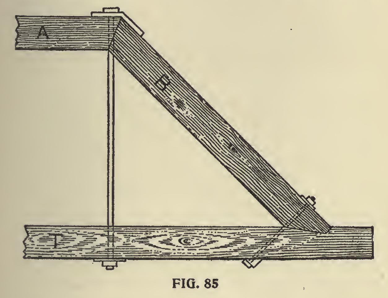
Fig. 86 represents the cross braces between the straining and tie beams. If the braces butt together as shown in the upper left hand corner of figure, the length and cuts are simply those for a common rafter having the same run and rise. Usually a block of hard wood is used for
the ends of the braces to rest against, as shown at the upper right hand corner, and in that case the angle may be found as for the brace against the beam.
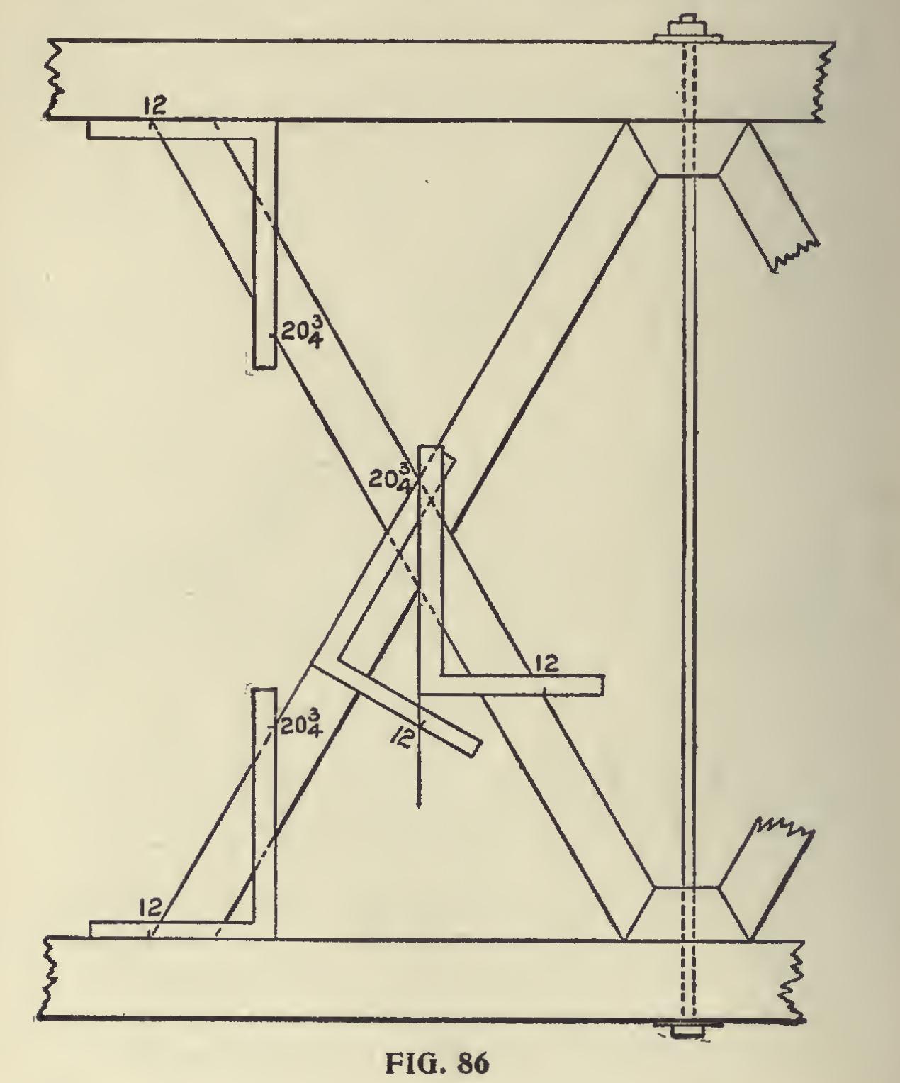
These braces are sometimes halved at the center to allow the sides of the braces to be flush with each other. The angle of cut is found by applying the square with the figures that give the plumb cut of a rafter of same pitch ; and to this without change of figures apply a second square as shown; this will give the proper angle across the brace from which to remove the wood.
Tower for Windmill, etc.
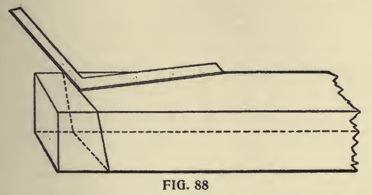
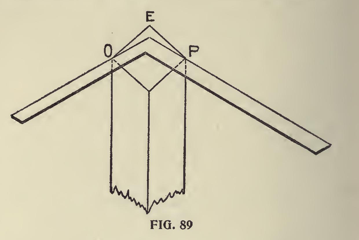
In connection with trusses we show in Fig. 87 a tower suitable for a windmill or for other similar purposes. The posts incline two inches to the foot—that is, two inches from the plumb line to every foot in the length of the post, and this incline is both ways. The length of post and bevels at the foot and top of posts may be found by applying the square as shown at R—that is, 24 inches on the blade and 4 inches on the tongue or 2 inches on the tongue and 12 inches on the blade, which is the same thing, so far as the bevels are con cerned. These same figures also answer for the ends of the joists, S-S. We show in Fig. 88 the manner in which the bevels at the foot of the posts are marked. The dotted lines show the bevels on all sides, for, as the post leans two ways, the post must be beveled two ways. This, of course, will present itself to the workman as lie proceeds. Let us suppose the foot of the post to have no tenon, but it is intended to rest flat footed on the sills. This being the case, it gives us an opportunity of getting the backing of the post, for, like a hip rafter—which it is—it requires to be backed, if it is intended to be enclosed or boarded, and we will suppose it is so intended. From an examination of Fig. 89 we can see how the backing of the post may be obtained by using the square and applying it on the foot after it has been cut. The overwood at E is to be re moved. In order to make the ends of the braces and cross pieces cut square against the corner posts, the latter should also be backed on the in side angle as well as on the outside, otherwise there would be little angle across the top of these braces to contend with, not much it is true, but enough to leave an open joint unless these pieces are cut to the angle. It will be noticed that the square is placed on the angles 0 and P, with its heel at E. The distance from E to P is the same as from E to 0. The overwood shown in this is somewhat exaggerated purposely, to give a clear idea of the requirements. The braces shown in this sketch will give the student an opportunity to figure. The lengths and bevels may be obtained either by using the square or by taking them from a drawing, or by calculation.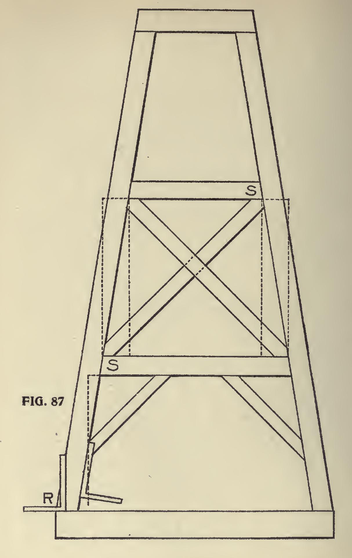
We may observe at this point, that the posts in this structure are simply like the hips in a very steep roof or spire, and in a measure may be treated as such, but it will be seen that while the posts rest in the same position as the hip in the roof, its sides do not rest parallel with the plate as they do in the case of the tower.