Hoppers and Hopper Bevels
square, tongue, pitch, shown, draw, board, angle and edge
To Find the Bevels Required to Miter Together the Flared Sides of a Hexagonal Hopper.ŚIn Fig. 70, let NE be in the plane of the bot tom of the hopper, and EJ the inclination of the sides; continue GD to B indefinitely; through J draw JO parallel to QD; through 0 draw AC at right angles to JO; make EM equal EJ; through M draw LC parallel to QD; make FH equal FJ; draw HA parallel to QD ; through F draw R13 parallel to LC; connect CD, and the bevel at D will give the angle for the face joint; connect BA, and the bevel at B will give the angle for the miter on the square edge. This rule may be applied to other figures, such as pentagons, octagons, or other similar hoppers, where the flares are equal.

Angles and Bevels for Hopper Work.ŚSome times the student may get in a little maze when working out the angles and bevels for hopper work, as the operation is often perplexing, and like the rules for stair-building, which will come a little later, requires patience and steadiness. There is no reason, however, because of these matters appearing difficult at first, that they should not be thoroughly understood by any ordinary workman, after two or three trials.
The following is from an article by Mr. A. W. Woods, published in a trade paper a short time ago: Hopper Cuts are similar to the cuts required for fitting boards in or over a valley or hip roof ; consequently the figures on the square that give the cuts for the roof boards must give the cut for a hopper of the same pitch.
Fig. 71 shows a hopper in different views, as follows: Beginning at the top is the top view of the hopper. As far as this part is concerned all hoppers are alike, as there is nothing in this to distinguish the pitch. Next is the sectional or side view. In this is shown the thickness of the boards and the flare or pitch, which in this is the three-quarters pitch. Next is shown the four sides in the collapsible or ready to be put together, followed with the top view of the edge of the board.
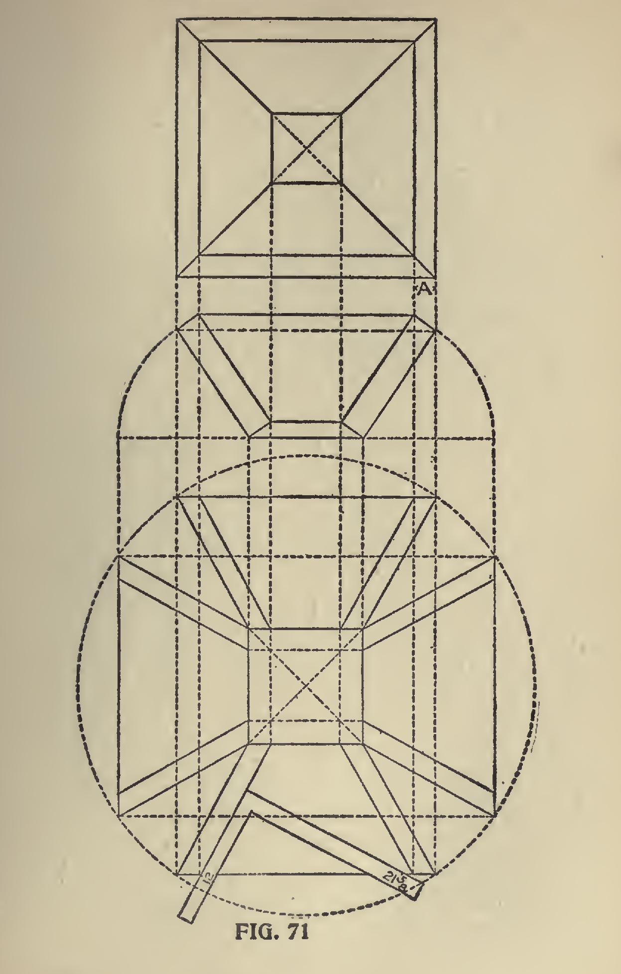
Of course it is not necessary to lay out all of this diagram, or any of it for that matter; it is done by way of illustration. See the application of the square, which, in this case, is 12 and 21 and five-eights. But why use these numbers? Because the flare given is the three-quarters pitch or 12 and 18 on the square, and the hypothenuse of these numbers is 21 and five-eights, the tongue giving the side bevel. When working full scale it is always 12 on the tongue.
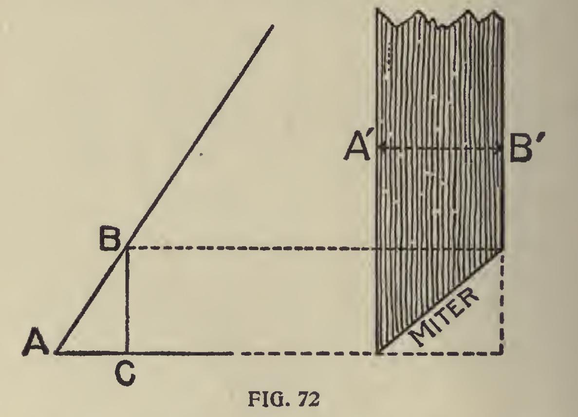
Miters.ŚFor the miter bevel, the top edges should be first beveled so as to be level when in position. The miter would be at an angle of 45 degrees, and any of the equal numbers on the square gives this cut; but if the edges are to be left square with the sides, as shown, the above will not work. To accomplish this, however,
it may be obtained as shown in diagram at A, by setting off the thickness along the edge of the board, or as shown in Fig. 72 as follows: Lay off the base and the desired pitch, and on the latter measure the thickness of the board as at AB. From B draw a plumb line to base. BC is the width apart; the side bevels should be along the edge of the board.
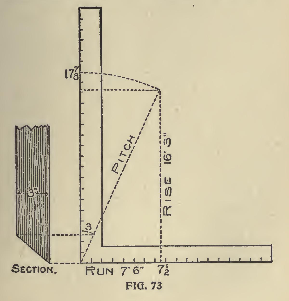
In case of large hoppers to be built to suit some particular place, or regardless of pitch, it is better to use the one-inch scale as illustrated in Fig. 73. For example, let 7 feet 6 inches be the run and 16 feet and 3 inches be the rise. Take 7i on the tongue and 17 and seven-eighths on the blade the tongue gives the cut across the face of the board. Take 17 and seven-eighths on the tongue and 16 and three-twelfths on the blade and the tongue gives the cut across the edge of the board to form the miter, or it may be found by diagram as shown in the section.
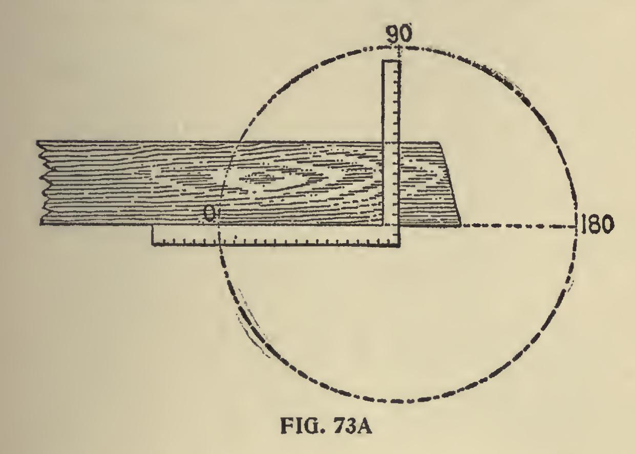
Methods of Finding the Miter.ŚGreat as the steel square may be in the hands of the learned mechanic, it is only secondary to the compasses. It simply steps in as an aid in defining what has already been determined by the compasses and their divisions called degrees. Therefore, we cannot pass the compasses by and the part they play without giving them due credit.
It will be our aim as far as possible to illustrate the part each instrument plays, thereby helping the student to more readily grasp the subject.
The old time masters, who set the recognized standard in architectural proportion, based their calculations upon the diameter of the circle and its divisions. Miters are governed by the divisions of the circumference of the circle, and not alone by the figures on the square. Therefore, to un lock the great fund of information contained in the arms of the square, it must be done by degrees. There are 360 contained in the circumference of the circle, and any of the regular polygonal miters can be readily found by dividing 360 by the num ber of sides in the polygon, and the quotient will be the angle that the miters stand with each other, but in order to obtain the angle with the steel square it is only necessary to take one-half of the degrees contained in the circle, or 180, and this divided by the number of sides in the polygon will give the degrees to use on the square. The reader will notice that we use 12 on the tongue for all miters; the reason we do this is because 12 represents unity. It may represent one inch, one foot, one yard, or any other scale of measure ment.